 |
a30zzw00002456
FRONT DOOR LATCH AND LOCK ACTUATOR REMOVAL/INSTALLATION
id091400200600
1. Fully close the front door glass.
2. Disconnect the negative lead-acid battery terminal. (See NEGATIVE LEAD-ACID BATTERY TERMINAL DISCONNECTION/CONNECTION.)
3. Remove the following parts.
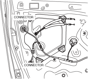
4. Disconnect the connectors.
a30zzw00002456
|
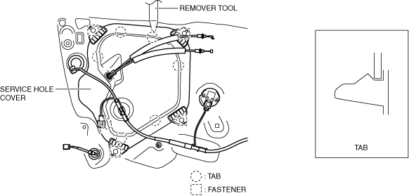
5. Remove the fasteners.
a30zzw00002457
|
6. Detach the service hole cover tabs from the body using a remover tool.
7. Remove the clips.
a30zzw00002458
|
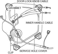
8. Remove the grommet.
9. Disconnect the door lock knob cable and inner handle cable from the service hole cover.
10. Remove the service hole cover. (See Service Hole Cover Installation Note.)
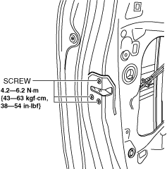
11. Remove the screws.
a30zzw00002459
|
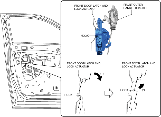
12. Tilt the front door latch and lock actuator in the direction of arrow (1) shown in the figure and lift it in the direction of arrow (2) to detach the front door latch and lock actuator hook from the body.
a30zzw00002460
|
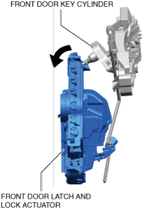
13. Tilt the front door latch and lock actuator in the direction of the arrow shown in the figure and pull out the front door key cylinder from the front door latch and lock actuator. (Driver's side)
a30zzw00002461
|
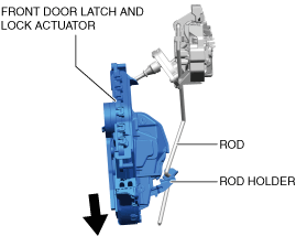
14. Lower the front door latch and lock actuator in the direction of the arrow shown in the figure, and pull out the rod from the rod holder.
a30zzw00002462
|
15. Remove the front door latch and lock actuator. (See Front Door Latch and Lock Actuator Installation Note.)
16. Install in the reverse order of removal.
Front Door Latch and Lock Actuator Installation Note
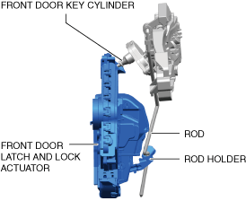
1. Verify that the front door key cylinder is assembled to the front door latch and lock actuator. (Driver's side)
a30zzw00002463
|
2. Move the rod back and forth and verify that it is inserted into the rod holder hole.
Service Hole Cover Installation Note
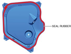
1. When installing the service hole cover, verify that the seal rubber is not wet.
a30zzw00002464
|