 |
a30zzw00001763
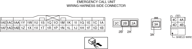
EMERGENCY CALL UNIT INSPECTION [(E)]
id0922007057x2
1. Disconnect the negative lead-acid battery terminal. (See NEGATIVE LEAD-ACID BATTERY TERMINAL DISCONNECTION/CONNECTION.)
2. Remove the passenger-side lower panel. (See PASSENGER-SIDE LOWER PANEL REMOVAL [(E)].)
3. Connect the negative lead-acid battery terminal. (See NEGATIVE LEAD-ACID BATTERY TERMINAL DISCONNECTION/CONNECTION.)
4. Measure the voltage at each terminal.
Terminal Voltage Table (Reference)
a30zzw00001763
|
|
Terminal |
Signal name |
Connected to |
Measurement conditions |
Voltage (V) |
Inspection item(s) |
|||
|---|---|---|---|---|---|---|---|---|
|
1A
|
IND1_P
|
Emergency call switch
|
Under any condition
|
5.0
|
• Emergency call switch
• Related wiring harness
|
|||
|
1B
|
SW1_P
|
Emergency call switch
|
Under any condition
|
5.0
|
• Emergency call switch
• Related wiring harness
|
|||
|
1C
|
IND2_P
|
Emergency call switch
|
Under any condition
|
5.0
|
• Emergency call switch
• Related wiring harness
|
|||
|
1D
|
SW_IND_N
|
Emergency call switch
|
Because this terminal is for communication, determination using terminal voltage inspection is not possible.
|
|||||
|
1E
|
MIC_PWR
|
Emergency call speaker/microphone
|
Under any condition
|
7.2—8.8
|
• Emergency call speaker/microphone
• Related wiring harness
|
|||
|
1F
|
—
|
—
|
—
|
—
|
—
|
|||
|
1G
|
MIC_IN_P
|
Emergency call speaker/microphone
|
Because this terminal is for communication, determination using terminal voltage inspection is not possible.
|
|||||
|
1H
|
—
|
—
|
—
|
—
|
—
|
|||
|
1I
|
MIC_IN_N
|
Emergency call speaker/microphone
|
Because this terminal is for communication, determination using terminal voltage inspection is not possible.
|
|||||
|
1J
|
MIC_GND
|
Emergency call speaker/microphone
|
Because this terminal is for communication, determination using terminal voltage inspection is not possible.
|
|||||
|
1K
|
MIC_OUT_P
|
Connectivity master unit (CMU)
|
Because this terminal is for communication, determination using terminal voltage inspection is not possible.
|
|||||
|
1L
|
PRE_OUT_N
|
Emergency call speaker/microphone
|
Because this terminal is for communication, determination using terminal voltage inspection is not possible.
|
|||||
|
1M
|
MIC_OUT_N
|
Connectivity master unit (CMU)
|
Because this terminal is for communication, determination using terminal voltage inspection is not possible.
|
|||||
|
1N
|
PRE_OUT_P
|
Emergency call speaker/microphone
|
Because this terminal is for communication, determination using terminal voltage inspection is not possible.
|
|||||
|
1O
|
GND1
|
Body ground
|
Under any condition
|
Approx. 0
|
• GND point
• Related wiring harness
|
|||
|
1P
|
—
|
—
|
—
|
—
|
—
|
|||
|
1Q
|
CAN_H_PBLC
|
CAN system related module
|
Because this terminal is for communication, determination using terminal voltage inspection is not possible.
|
|||||
|
1R
|
GND3
|
Body ground
|
Under any condition
|
Approx. 0
|
• GND point
• Related wiring harness
|
|||
|
1S
|
CAN_L_PBLC
|
CAN system related module
|
Because this terminal is for communication, determination using terminal voltage inspection is not possible.
|
|||||
|
1T
|
GND4
|
Body ground
|
Under any condition
|
Approx. 0
|
• GND point
• Related wiring harness
|
|||
|
1U
|
GND2
|
Body ground
|
Under any condition
|
Approx. 0
|
• GND point
• Related wiring harness
|
|||
|
1V
|
—
|
—
|
—
|
—
|
—
|
|||
|
1W
|
MIC_MODE_UART_CMU
|
Connectivity master unit (CMU)
|
Because this terminal is for communication, determination using terminal voltage inspection is not possible.
|
|||||
|
1X
|
MOST_WAKEUP_IN
|
Connectivity master unit (CMU)
|
Because this terminal is for communication, determination using terminal voltage inspection is not possible.
|
|||||
|
1Y
|
MIC_MODE_UART_MIC
|
Emergency call speaker/microphone
|
Because this terminal is for communication, determination using terminal voltage inspection is not possible.
|
|||||
|
1Z
|
MOST_WAKEUP_OUT
|
Audio amplifier
|
Because this terminal is for communication, determination using terminal voltage inspection is not possible.
|
|||||
|
1AA
|
ENS2_IN
|
SAS control module
|
Because this terminal is for communication, determination using terminal voltage inspection is not possible.
|
|||||
|
1AB
|
—
|
—
|
—
|
—
|
—
|
|||
|
1AC
|
ENS2_OUT
|
Door-electrical supply unit (driver’s side)
|
Because this terminal is for communication, determination using terminal voltage inspection is not possible.
|
|||||
|
1AD
|
—
|
—
|
—
|
—
|
—
|
|||
|
1AE
|
IG1
|
F48 7.5A fuse
|
Switch the main power ON (READY off or on)
|
B+
|
• F48 7.5A fuse
• Related wiring harness
|
|||
|
Switch the main power OFF
|
1.0 or less
|
|||||||
|
1AF
|
BATT
|
F46 15 A fuse
|
Under any condition
|
B+
|
• F46 15 A fuse
• Lead-acid battery
• Related wiring harness
|
|||
|
2A
|
TEL_SIG1
|
TEL antenna No.1
|
Because this terminal is for communication, determination using terminal voltage inspection is not possible.
|
|||||
|
2B
|
GNSS_SIG
|
TEL antenna No.1
|
Because this terminal is for communication, determination using terminal voltage inspection is not possible.
|
|||||
|
3A
|
TEL_SIG2
|
TEL antenna No.2
|
Because this terminal is for communication, determination using terminal voltage inspection is not possible.
|
|||||
|
4A
|
USB1_GND
|
Connectivity master unit (CMU)
|
Under any condition
|
1.0 or less
|
• Connectivity master unit (CMU)
• Related wiring harness
|
|||
|
4B
|
USB1_DATA_P
|
Connectivity master unit (CMU)
|
Because this terminal is for communication, determination using terminal voltage inspection is not possible.
|
|||||
|
4C
|
USB1_VBUS
|
Connectivity master unit (CMU)
|
Under any condition
|
Approx. 5.0
|
• Connectivity master unit (CMU)
• Related wiring harness
|
|||
|
4D
|
USB1_DATA_N
|
Connectivity master unit (CMU)
|
Because this terminal is for communication, determination using terminal voltage inspection is not possible.
|
|||||