 |
a30zzw00004602
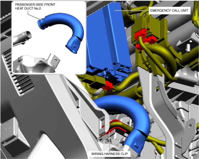
EMERGENCY CALL UNIT REMOVAL/INSTALLATION [(E)]
id0922007022x2
Replacement parts
|
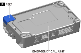
Felt
Quantity: 1
Location of use: Emergency call unit
|
L.H.D.
1. Remove the selector lever knob. (See SELECTOR LEVER REMOVAL/INSTALLATION [A71M].)
2. Disconnect the negative lead-acid battery terminal. (See NEGATIVE LEAD-ACID BATTERY TERMINAL DISCONNECTION/CONNECTION.)
3. Remove the following parts.
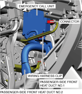
4. Remove passenger-side front heat duct No.2.
a30zzw00004602
|
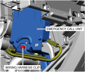
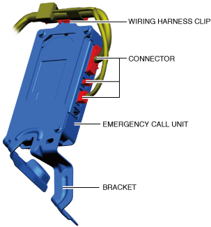
5. Remove the wiring harness clip.
6. Disconnect the connectors.
7. Insert a flathead screwdriver into the position shown in the figure and detach the tabs from connector A.
a30zzw00004603
|
8. Remove connector A in the direction of arrow (1).
9. Insert a flathead screwdriver into the position shown in the figure and detach the tabs from connector B.
10. Remove connector B in the direction of arrow (2).
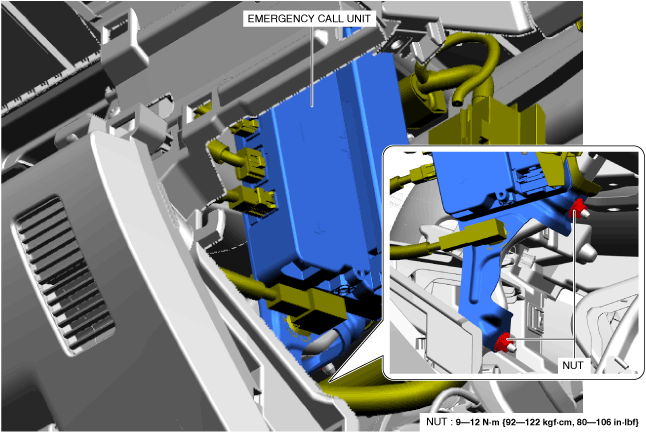
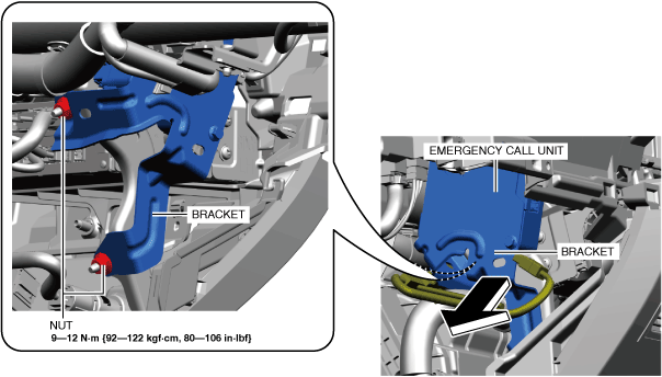
11. Remove the nuts.
a30zzw00003333
|
12. Remove the emergency call unit and the bracket as a single unit.
13. Disconnect the connectors.
a30zzw00003444
|
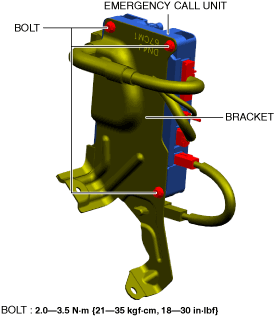
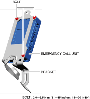
14. Remove the bolts.
15. Remove the emergency call unit.
16. Install in the reverse order of removal. (See Emergency Call Unit Installation Note.)
17. If the emergency call unit is replaced, perform the procedure after the emergency call unit replacement. (See Procedure After Emergency Call Unit Replacement.)
R.H.D.
1. Remove the selector lever knob. (See SELECTOR LEVER REMOVAL/INSTALLATION [A71M].)
2. Disconnect the negative lead-acid battery terminal. (See NEGATIVE LEAD-ACID BATTERY TERMINAL DISCONNECTION/CONNECTION.)
3. Remove the following parts.
4. Disconnect the passenger-side front heat duct No.2 from the passenger-side front heat duct No.1.
a30zzw00006803
|
5. Remove the wiring harness clips.
6. Disconnect the connector.
7. Remove the wiring harness clip.
a30zzw00006804
|
8. Remove the nuts.
a30zzw00006805
|
9. Move the emergency call unit in the direction of arrow shown in the figure.
10. Disconnect the connectors.
a30zzw00006806
|
11. Remove the wiring harness clip.
12. Remove the emergency call unit and the bracket as a single unit.
13. Remove the bolts.
a30zzw00006807
|
14. Remove the emergency call unit.
15. Install in the reverse order of removal. (See Emergency Call Unit Installation Note.)
16. If the emergency call unit is replaced, perform the procedure after the emergency call unit replacement. (See Procedure After Emergency Call Unit Replacement.)
Procedure After Emergency Call Unit Replacement
Connected Service is not contracted
1. Switch the main power ON (READY off) to complete the global central configuration (GCC) for the emergency call unit.
2. Clear the DTC. (See CLEARING DTC.)
3. Cancel connected services disable mode. (When transitioning to connected services disable mode) (See SERVICE CAUTIONS FOR VEHICLES WITH EMERGENCY CALL SYSTEM [(E)].)
4. Cancel connected vehicle maintenance mode. (When transitioning to connected vehicle maintenance mode) (See SERVICE CAUTIONS FOR VEHICLES WITH EMERGENCY CALL SYSTEM [(E)].)
5. Perform the activating remote control by smart phone. (See ACTIVATING REMOTE CONTROL BY SMART PHONE.)
Connected Service is contracted
1. Switch the main power ON (READY off) to complete the global central configuration (GCC) for the emergency call unit.
2. Clear the DTC. (See CLEARING DTC.)
3. Cancel connected services disable mode. (When transitioning to connected services disable mode) (See SERVICE CAUTIONS FOR VEHICLES WITH EMERGENCY CALL SYSTEM [(E)].)
4. Cancel connected vehicle maintenance mode. (When transitioning to connected vehicle maintenance mode) (See SERVICE CAUTIONS FOR VEHICLES WITH EMERGENCY CALL SYSTEM [(E)].)
5. Perform the activating remote control by smart phone. (See ACTIVATING REMOTE CONTROL BY SMART PHONE.)
6. Perform the emergency call unit initial setting. (See EMERGENCY CALL UNIT INITIAL SETTING [(E)].)
7. Switch the main power OFF and wait for 5 min or more.
8. Switch the main power ON (READY off or on) and wait for 1 min or more.
9. Launch the diagnostic assist function. (Refer to the [DIAGNOSTIC ASSIST FUNCTION [CONNECTIVITY MASTER UNIT]] in the workshop manual.)
10. Select [Service Information] on the diagnostic assist function initial screen.
11. Select [TCU Linked Information] on the [Service Information] screen.
12. Verify that the remote service flag in the [Remote Service Flag Information] indicates [1] as shown in the figure.
a30zzw00006781
|
13. Switch the main power OFF.
Emergency Call Unit Installation Note
a30zzw00004682
|