 |
a30zzw00006589
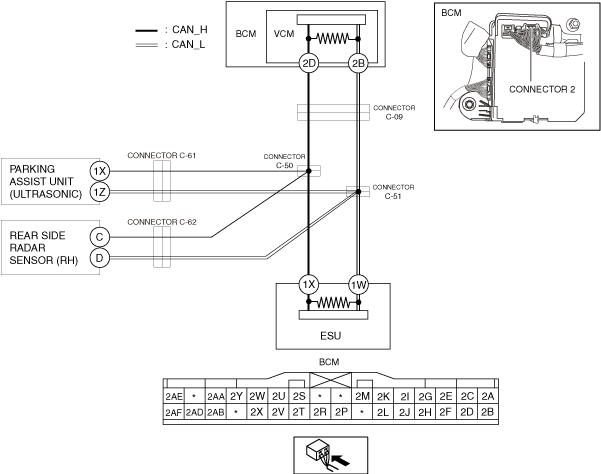
DETERMINING SHORT TO GROUND LOCATION (CAN-BUS No.4) [L.H.D.]
id100225003000
System Wiring Diagram
a30zzw00006589
|
Determination Procedure
|
Step |
Inspection |
Action |
|
|---|---|---|---|
|
1
|
INSPECT FOR SHORT TO GROUND BETWEEN BODY CONTROL MODULE (BCM) AND CONNECTOR C-09
• Switch the main power OFF.
• Disconnect the negative lead-acid battery terminal.
• Disconnect the connector C-09.
• Inspect for continuity at the following terminals:
• Is there continuity?
|
Yes
|
Go to the next step.
|
|
No
|
Go to Step 3.
|
||
|
2
|
INSPECT CAN LINE IN BODY CONTROL MODULE (BCM) FOR SHORT TO GROUND
• Disconnect the connector 2 which has body control module (BCM) terminals 2D and 2B.
• Inspect for continuity at the following terminals:
• Is there continuity?
|
Yes
|
Repair or replace the wiring harness between the connector C-09 and body control module (BCM) because the wiring harness is shorted to ground.
|
|
No
|
Replace the body control module (BCM) because there is a short to ground in the body control module (BCM).
|
||
|
3
|
INSPECT FOR SHORT TO GROUND BETWEEN CONNECTOR C-09 AND CONNECTORS C-50, C-51
• Disconnect the connectors C-50, C-51.
• Connect the connector C-09.
• Inspect for continuity at the following terminals:
• Is there continuity?
|
Yes
|
Repair or replace the wiring harness between the connector C-09 and connectors C-50, C-51 because the wiring harness is shorted to ground.
|
|
No
|
Go to the next step.
|
||
|
4
|
INSPECT FOR SHORT TO GROUND BETWEEN PARKING ASSIST UNIT (ULTRASONIC) AND CONNECTORS C-50, C-51
• Inspect for continuity at the following terminals:
• Is there continuity?
|
Yes
|
Go to the next step.
|
|
No
|
Go to Step 7.
|
||
|
5
|
INSPECT FOR SHORT TO GROUND BETWEEN PARKING ASSIST UNIT (ULTRASONIC) AND CONNECTOR C-61
• Disconnect the connector C-61.
• Inspect for continuity at the following terminals:
• Is there continuity?
|
Yes
|
Go to the next step.
|
|
No
|
Repair or replace the wiring harness between the connector C-61 and connectors C-50, C-51 because the wiring harness is shorted to ground.
|
||
|
6
|
INSPECT CAN LINE IN PARKING ASSIST UNIT (ULTRASONIC) FOR SHORT TO GROUND
• Disconnect the parking assist unit (ultrasonic) connector.
• Inspect for continuity at the following terminals:
• Is there continuity?
|
Yes
|
Repair or replace the wiring harness between the connector C-61 and parking assist unit (ultrasonic) because the wiring harness is shorted to ground.
|
|
No
|
Replace the parking assist unit (ultrasonic) because there is a short to ground in the parking assist unit (ultrasonic).
|
||
|
7
|
INSPECT FOR SHORT TO GROUND BETWEEN REAR SIDE RADAR SENSOR (RH) AND CONNECTORS C-50, C-51
• Inspect for continuity at the following terminals:
• Is there continuity?
|
Yes
|
Go to the next step.
|
|
No
|
Go to Step 10.
|
||
|
8
|
INSPECT FOR SHORT TO GROUND BETWEEN REAR SIDE RADAR SENSOR (RH) AND CONNECTOR C-62
• Disconnect the connector C-62.
• Inspect for continuity at the following terminals:
• Is there continuity?
|
Yes
|
Go to the next step.
|
|
No
|
Repair or replace the wiring harness between the connector C-62 and connectors C-50, C-51 because the wiring harness is shorted to ground.
|
||
|
9
|
INSPECT CAN LINE IN REAR SIDE RADAR SENSOR (RH) FOR SHORT TO GROUND
• Disconnect the rear side radar sensor (RH) connector.
• Inspect for continuity at the following terminals:
• Is there continuity?
|
Yes
|
Repair or replace the wiring harness between connector C-62 and rear side radar sensor (RH) because the wiring harness is shorted to ground.
|
|
No
|
Replace the rear side radar sensor (RH) because there is a short to ground in the rear side radar sensor (RH).
|
||
|
10
|
INSPECT CAN LINE IN ELECTRICAL SUPPLY UNIT (ESU) FOR SHORT TO GROUND
• Disconnect the electrical supply unit (ESU) connector.
• Inspect for continuity at the following terminals:
• Is there continuity?
|
Yes
|
Repair or replace the wiring harness between the electrical supply unit (ESU) and connectors C-50, C-51 because the wiring harness is shorted to ground.
|
|
No
|
Replace the electrical supply unit (ESU) because there is a short to ground in the electrical supply unit (ESU).
|
||