 |
a30zzw00006600
DETERMINING SHORT BETWEEN CIRCUITS LOCATION (CAN-BUS No.5) [L.H.D. (E)]
id100225003676
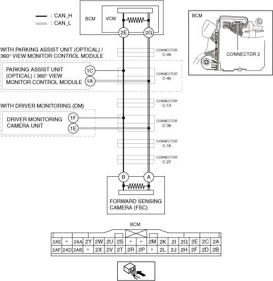
System Wiring Diagram
a30zzw00006600
|
Determination Procedure
|
Step |
Inspection |
Action |
|
|---|---|---|---|
|
1
|
INSPECT BODY CONTROL MODULE (BCM) FOR SHORT BETWEEN CIRCUITS
• Switch the main power OFF.
• Disconnect the negative lead-acid battery terminal.
• Disconnect the connector 2 which has body control module (BCM) terminals 2E and 2G.
• Connect the negative lead-acid battery terminal.
• Switch the main power ON (READY off).
• Measure the voltage at body control module (BCM) terminals 2E and 2G (wiring harness side).
• Is the voltage at body control module (BCM) terminals 2E and 2G (wiring harness side) the same?
|
Yes
|
Go to the next step.
|
|
No
|
Replace the body control module (BCM) because there is a short between circuits in the body control module (BCM).
|
||
|
2
|
INSPECT CAN LINE BETWEEN CONNECTOR C-06 AND BODY CONTROL MODULE (BCM) FOR SHORT BETWEEN CIRCUITS
• Switch the main power OFF.
• Disconnect the negative lead-acid battery terminal.
• Disconnect the connector C-06.
• Connect the connector 2 which has body control module (BCM) terminals 2E and 2G.
• Connect the negative lead-acid battery terminal.
• Switch the main power ON (READY off).
• Measure the voltage at body control module (BCM) terminals 2E and 2G.
• Is the voltage at body control module (BCM) terminals 2E and 2G the same?
|
Yes
|
Repair or replace the wiring harness between the body control module (BCM) and connector C-06 because the wiring harness is shorted between circuits.
|
|
No
|
• Go to the next step. (With parking assist unit (optical) / 360° view monitor control module)
• Go to Step 7. (Without parking assist unit (optical) / 360° view monitor control module)
|
||
|
3
|
INSPECT CAN LINE BETWEEN CONNECTOR C-40 AND CONNECTOR C-06 FOR SHORT BETWEEN CIRCUITS
• Switch the main power OFF.
• Disconnect the negative lead-acid battery terminal.
• Disconnect the connector C-40.
• Connect the connector C-06.
• Connect the negative lead-acid battery terminal.
• Switch the main power ON (READY off).
• Measure the voltage at body control module (BCM) terminals 2E and 2G.
• Is the voltage at body control module (BCM) terminals 2E and 2G the same?
|
Yes
|
Repair or replace the wiring harness between connector C-40 and connector C-06 because the wiring harness is shorted between circuits.
|
|
No
|
Go to the next step.
|
||
|
4
|
INSPECT CAN LINE BETWEEN PARKING ASSIST UNIT (OPTICAL) / 360° VIEW MONITOR CONTROL MODULE AND CONNECTOR C-40 FOR SHORT BETWEEN CIRCUITS
• Switch the main power OFF.
• Disconnect the negative lead-acid battery terminal.
• Inspect for continuity between parking assist unit (optical) / 360° view monitor control module terminals 1C and 1A.
• Is there continuity?
|
Yes
|
Go to the next step.
|
|
No
|
Go to Step 6.
|
||
|
5
|
INSPECT PARKING ASSIST UNIT (OPTICAL) / 360° VIEW MONITOR CONTROL MODULE FOR SHORT BETWEEN CIRCUITS
• Disconnect the parking assist unit (optical) / 360° view monitor control module connector.
• Inspect for continuity between parking assist unit (optical) / 360° view monitor control module terminals 1C and 1A (wiring harness side).
• Is there continuity?
|
Yes
|
Repair or replace the wiring harness between the parking assist unit (optical) / 360° view monitor control module and connector C-40 because the wiring harness is shorted between circuits.
|
|
No
|
Replace the parking assist unit (optical) / 360° view monitor control module because there is a short between circuits in the parking assist unit (optical) / 360° view monitor control module.
|
||
|
6
|
INSPECT CAN LINE BETWEEN CONNECTOR C-13 AND CONNECTOR C-40 FOR SHORT BETWEEN CIRCUITS
• Disconnect the connector C-13.
• Connect the connector C-40.
• Connect the negative lead-acid battery terminal.
• Switch the main power ON (READY off).
• Measure the voltage at body control module (BCM) terminals 2E and 2G.
• Is the voltage at body control module (BCM) terminals 2E and 2G the same?
|
Yes
|
Repair or replace the wiring harness between connector C-13 and connector C-40 because the wiring harness is shorted between circuits.
|
|
No
|
Go to Step 8.
|
||
|
7
|
INSPECT CAN LINE BETWEEN CONNECTOR C-06 AND CONNECTOR C-13 FOR SHORT BETWEEN CIRCUITS
• Switch the main power OFF.
• Disconnect the negative lead-acid battery terminal.
• Disconnect the connector C-13.
• Connect the connector C-06.
• Connect the negative lead-acid battery terminal.
• Switch the main power ON (READY off).
• Measure the voltage at body control module (BCM) terminals 2E and 2G.
• Is the voltage at body control module (BCM) terminals 2E and 2G the same?
|
Yes
|
Repair or replace the wiring harness between connector C-06 and connector C-13 because the wiring harness is shorted between circuits.
|
|
No
|
Go to the next step.
|
||
|
8
|
INSPECT CAN LINE BETWEEN CONNECTOR C-38 AND CONNECTOR C-13 FOR SHORT BETWEEN CIRCUITS
• Switch the main power OFF.
• Disconnect the negative lead-acid battery terminal.
• Disconnect the connector C-38.
• Connect the connector C-13.
• Connect the negative lead-acid battery terminal.
• Switch the main power ON (READY off).
• Measure the voltage at body control module (BCM) terminals 2E and 2G.
• Is the voltage at body control module (BCM) terminals 2E and 2G the same?
|
Yes
|
Repair or replace the wiring harness between connector C-13 and connector C-38 because the wiring harness is shorted between circuits.
|
|
No
|
• Go to the next step. (With driver monitoring camera unit)
• Go to Step 11. (Without driver monitoring camera unit)
|
||
|
9
|
INSPECT CAN LINE BETWEEN DRIVER MONITORING CAMERA UNIT AND CONNECTOR C-38 FOR SHORT BETWEEN CIRCUITS
• Switch the main power OFF.
• Disconnect the negative lead-acid battery terminal.
• Inspect for continuity between driver monitoring camera unit terminals 1F and 1E.
• Is there continuity?
|
Yes
|
Go to the next step.
|
|
No
|
Go to Step 11.
|
||
|
10
|
INSPECT DRIVER MONITORING CAMERA UNIT FOR SHORT BETWEEN CIRCUITS
• Disconnect the driver monitoring camera unit connector.
• Inspect for continuity between driver monitoring camera unit terminals 1F and 1E (wiring harness side).
• Is there continuity?
|
Yes
|
Repair or replace the wiring harness between the driver monitoring camera unit and connector C-38 because the wiring harness is shorted between circuits.
|
|
No
|
Replace the driver monitoring camera unit because there is a short between circuits in the driver monitoring camera unit.
|
||
|
11
|
INSPECT CAN LINE BETWEEN CONNECTOR C-16 AND CONNECTOR C-38 FOR SHORT BETWEEN CIRCUITS
• Disconnect the connector C-16.
• Connect the connector C-38.
• Connect the negative lead-acid battery terminal.
• Switch the main power ON (READY off).
• Measure the voltage at body control module (BCM) terminals 2E and 2G.
• Is the voltage at body control module (BCM) terminals 2E and 2G the same?
|
Yes
|
Repair or replace the wiring harness between connector C-16 and connector C-38 because the wiring harness is shorted between circuits.
|
|
No
|
Go to the next step.
|
||
|
12
|
INSPECT CAN LINE BETWEEN CONNECTOR C-27 AND CONNECTOR C-16 FOR SHORT BETWEEN CIRCUITS
• Switch the main power OFF.
• Disconnect the negative lead-acid battery terminal.
• Disconnect the connector C-27.
• Connect the connector C-16.
• Connect the negative lead-acid battery terminal.
• Switch the main power ON (READY off).
• Measure the voltage at body control module (BCM) terminals 2E and 2G.
• Is the voltage at body control module (BCM) terminals 2E and 2G the same?
|
Yes
|
Repair or replace the wiring harness between connector C-27 and connector C-16 because the wiring harness is shorted between circuits.
|
|
No
|
Go to the next step.
|
||
|
13
|
INSPECT FORWARD SENSING CAMERA (FSC) FOR SHORT BETWEEN CIRCUITS
• Switch the main power OFF.
• Disconnect the negative lead-acid battery terminal.
• Disconnect the forward sensing camera (FSC) connector.
• Inspect for continuity between forward sensing camera (FSC) terminals B and A (wiring harness side).
• Is there continuity?
|
Yes
|
Repair or replace the wiring harness between the forward sensing camera (FSC) and connector C-27 because the wiring harness is shorted between circuits.
|
|
No
|
Replace the forward sensing camera (FSC) because there is a short between circuits in the forward sensing camera (FSC).
|
||