 |
a30zzw00006612
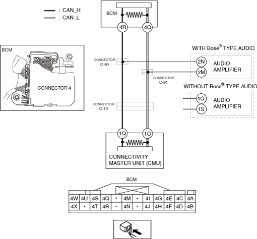
DETERMINING SHORT TO POWER SUPPLY LOCATION (CAN-BUS No.7) [R.H.D.]
id100226004300
System Wiring Diagram
a30zzw00006612
|
Determination Procedure
|
Step |
Inspection |
Action |
|
|---|---|---|---|
|
1
|
INSPECT CAN LINE BETWEEN CONNECTORS C-80, C-81 AND BODY CONTROL MODULE (BCM) FOR SHORT TO POWER SUPPLY
• Switch the main power OFF.
• Disconnect the negative lead-acid battery terminal.
• Disconnect the connectors C-80, C-81.
• Connect the negative lead-acid battery terminal.
• Switch the main power ON (READY off).
• Measure the voltage at body control module (BCM) terminals 4R and 4Q.
• Is the voltage between 1.5—3.5 V?
|
Yes
|
Go to Step 3.
|
|
No
|
Go to the next step.
|
||
|
2
|
INSPECT BODY CONTROL MODULE (BCM) FOR SHORT TO POWER SUPPLY
• Switch the main power OFF.
• Disconnect the negative lead-acid battery terminal.
• Disconnect the connector 4 which has body control module (BCM) terminals 4R and 4Q.
• Connect the connectors C-80, C-81.
• Connect the negative lead-acid battery terminal.
• Switch the main power ON (READY off).
• Measure the voltage at body control module (BCM) terminals 4R and 4Q (wiring harness side).
• Is the voltage between 1.5—3.5 V?
|
Yes
|
Replace the body control module (BCM) because there is a short to the power supply in the body control module (BCM).
|
|
No
|
Repair or replace the wiring harness between the body control module (BCM) and connectors C-80, C-81 because the wiring harness is shorted to the power supply.
|
||
|
3
|
INSPECT CAN LINE BETWEEN AUDIO AMPLIFIER AND CONNECTORS C-80, C-81 FOR SHORT TO POWER SUPPLY
• Measure the voltage at audio amplifier terminals 2N and 2M. (With Bose® type audio)
• Measure the voltage at audio amplifier terminals 1Q and 1S. (Without Bose® type audio)
• Is the voltage between 1.5—3.5 V?
|
Yes
|
Go to Step 5.
|
|
No
|
Go to the next step.
|
||
|
4
|
INSPECT AUDIO AMPLIFIER FOR SHORT TO POWER SUPPLY
• Switch the main power OFF.
• Disconnect the negative lead-acid battery terminal.
• Disconnect the audio amplifier connector.
• Connect the connectors C-80, C-81.
• Connect the negative lead-acid battery terminal.
• Switch the main power ON (READY off).
• Measure the voltage at body control module (BCM) terminals 4R and 4Q.
• Is the voltage between 1.5—3.5 V?
|
Yes
|
Replace the audio amplifier because there is a short to the power supply in the audio amplifier.
|
|
No
|
Repair or replace the wiring harness between the audio amplifier and connectors C-80, C-81 because the wiring harness is shorted to the power supply.
|
||
|
5
|
INSPECT CAN LINE BETWEEN CONNECTORS C-80, C-81 AND CONNECTOR C-13 FOR SHORT TO POWER SUPPLY
• Switch the main power OFF.
• Disconnect the negative lead-acid battery terminal.
• Connect the connectors C-80, C-81.
• Disconnect the connector C-13.
• Connect the negative lead-acid battery terminal.
• Switch the main power ON (READY off).
• Measure the voltage at body control module (BCM) terminals 4R and 4Q.
• Is the voltage between 1.5—3.5 V?
|
Yes
|
Go to the next step.
|
|
No
|
Repair or replace the wiring harness between the connectors C-80, C-81 and connector C-13 because the wiring harness is shorted to the power supply.
|
||
|
6
|
INSPECT CONNECTIVITY MASTER UNIT (CMU) FOR SHORT TO POWER SUPPLY
• Switch the main power OFF.
• Disconnect the negative lead-acid battery terminal.
• Disconnect the connectivity master unit (CMU) connector.
• Connect the connector C-13.
• Connect the negative lead-acid battery terminal.
• Switch the main power ON (READY off).
• Measure the voltage at body control module (BCM) terminals 4R and 4Q.
• Is the voltage between 1.5—3.5 V?
|
Yes
|
Replace the connectivity master unit (CMU) because there is a short to the power supply in the connectivity master unit (CMU).
|
|
No
|
Repair or replace the wiring harness between the connectivity master unit (CMU) and connector C-13 because the wiring harness is shorted to the power supply.
|
||