 |
a30zzw00006615
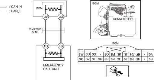
DETERMINING SHORT TO GROUND LOCATION (CAN-BUS No.8) [R.H.D.]
id100226004600
System Wiring Diagram
a30zzw00006615
|
Determination Procedure
|
Step |
Inspection |
Action |
|
|---|---|---|---|
|
1
|
INSPECT CAN LINE IN BODY CONTROL MODULE (BCM) FOR SHORT TO GROUND
• Switch the main power OFF.
• Disconnect the negative lead-acid battery terminal.
• Disconnect the connector 3 which has body control module (BCM) terminals 3V and 3U.
• Inspect for continuity at the following terminals:
• Is there continuity?
|
Yes
|
Go to the next step.
|
|
No
|
Replace the body control module (BCM) because there is a short to ground in the body control module (BCM).
|
||
|
2
|
INSPECT FOR SHORT TO GROUND BETWEEN CONNECTOR C-19 AND BODY CONTROL MODULE (BCM)
• Disconnect the connector C-19.
• Connect the connector 3 which has body control module (BCM) terminals 3V and 3U.
• Inspect for continuity at the following terminals:
• Is there continuity?
|
Yes
|
Repair or replace the wiring harness between the connector C-19 and body control module (BCM) because the wiring harness is shorted to ground.
|
|
No
|
Go to the next step.
|
||
|
3
|
INSPECT CAN LINE IN EMERGENCY CALL UNIT FOR SHORT TO GROUND
• Disconnect the emergency call unit connector.
• Inspect for continuity at the following terminals:
• Is there continuity?
|
Yes
|
Repair or replace the wiring harness between the emergency call unit and connector C-19 because the wiring harness is shorted to ground.
|
|
No
|
Replace the emergency call unit because there is a short to ground in the emergency call unit.
|
||