INVERTER
id301000200100
Purpose
• The direct current power supplied by the high voltage battery is converted to alternating current power for driving the motor.
In addition, the alternating current power supplied by the motor during deceleration is converted to direct current power for charging the high voltage battery.
Functions
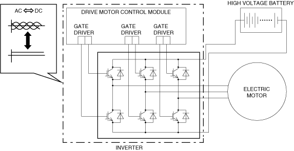
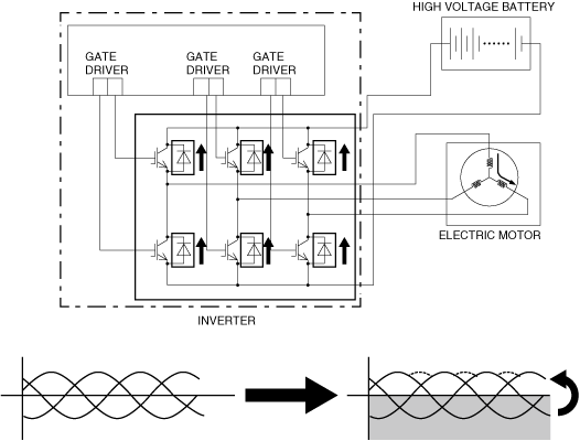
• The inverter converts direct current power to alternating current power by controlling the direct current power frequency.
• The inverter incorporates a three-phase bridge circuit using a power transistor to perform conversion between direct current power and alternate current power.
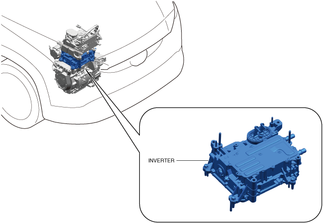
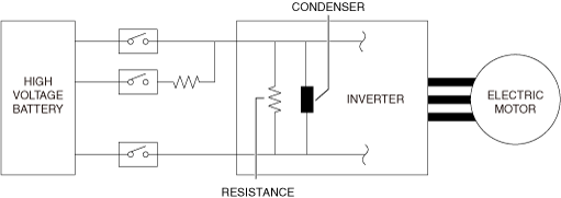
Construction
• The inverter is located on top of the electric motor.
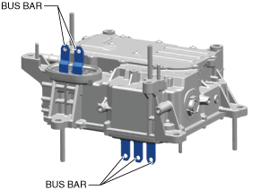
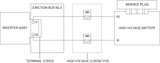
• The electrical power from the high voltage battery is input through the junction box No.3. (See
JUNCTION BOX No.3.)
• The inverter is electrically connected with the electric motor and the junction box No.3 using bus bars.
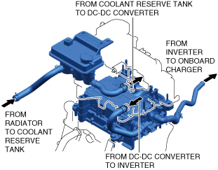
• Because the inverter generates heat when converting direct current power and alternating current power, a coolant passage is installed inside the inverter to cool the parts.
• A high voltage contactor is equipped in the circuit between the inverter and the high voltage battery. When the high voltage contactor is on, electrical power is supplied from the high voltage battery to the inverter. (See
HIGH VOLTAGE CIRCUIT START/CUT OFF CONTROL.)
• The inverter incorporates a condenser and a discharge resistance.
-
― Condenser
-
• The condenser prevents surge voltage which occurs when the high voltage contactors are connected and it eliminates switching noise of the power transistor.
-
― Discharge resistance
-
• When the main power is switched OFF (READY off), the remaining electrical power in the high voltage circuit is discharged by load resistance to assure safety of the high voltage circuit.
• The inverter has a built-in drive motor control module. The drive motor control module controls and monitors the electric driving system. (See
ELECTRIC DRIVE SYSTEM CONTROL.)
• The inverter consists of a three-phase bridge circuit using 6 power transistors and 6 diodes in the inverter.
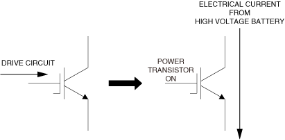
Power transistor
• A power transistor is a semiconductor element used in an electronic circuit which controls large electrical power.
• It generates heat because it connects and blocks a large amount of current. Coolant is used for cooling to reduce damage or loss of efficiency caused by heat.
• The power transistors operate according to drive signals from the gate drivers, and supplies or blocks the electrical power from the high voltage battery to the stator coils.
-
― When the drive motor control module outputs drive signals to the gate drivers, the drive voltage is input from the gate drivers to the power transistors to turn them on.
― By the power transistors being turned on, the high voltage battery electrical current is supplied to the stator coils of the electric motor.
Operation
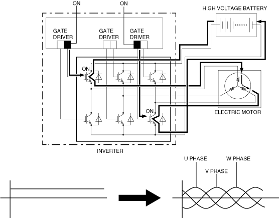
During driving
1. When the drive motor control module outputs drive signals to the gate drivers, the drive voltage is input from the gate drivers to the power transistors to turn them on.
2. When the power transistors turn on, the current from the high voltage battery flows from upstream to downstream.
3. By switching the power transistors on/off intermittently to control the current frequency, alternating current is generated in the stator coils.
4. The alternating current is sent to the stator coil of each phase of the electric motor by changing the combination of the 6 power transistors.
5. By performing the duty control of the power transistors, alternating current close to sine wave alternating current is generated in the stator coils.
During regenerative braking
1. The alternating current is generated by the electric motor rotation.
2. By sending the alternating current through the diodes in the inverter, three-phase full wave rectification is performed and the alternating current is converted to direct current.
3. The converted direct current is input to the high voltage battery to charge the high voltage battery.
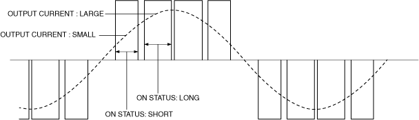
Current Control
-
• For the required torque calculated according to the driving conditions and driver operation, the output electrical current command value is determined and the power transistor duty ratio is controlled so that the command value is reached.
Output current: Large
-
― By increasing the rate of the on time of the power transistor, the output current is increased. As a result, the motor torque is increased.
Output current: Small
-
― By decreasing the rate of the on time of the power transistor, the output current is decreased. As a result, the motor torque is decreased.
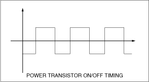
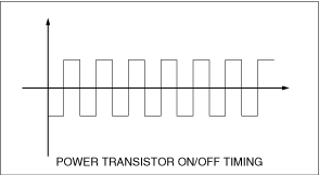
Frequency control
-
• The electric motor rotation speed is controlled by changing the on/off switching frequency of the power transistors, which changes the frequency of the duty rate.
• When the frequency is decreased, the electric motor rotation speed is decreased, and when the frequency is increased, the electric motor rotation speed is increased.
-
Rotation speed: Decrease
-
• When the on/off switching frequency of the power transistors is decreased, the alternating current frequency is decreased, which decreases the electric motor rotation speed..
-
Rotation speed: Increase
-
• When the on/off switching frequency of the power transistors is increased, the alternating current frequency is increased, which increases the electric motor rotation speed.