COOLANT REPLACEMENT
id301200000400
Replacement part
|
Coolant
Type: Recommended coolant
|
-
Warning
-
• The EV system is hot immediately after driving and charging, and can cause severe burns. Turn off the EV system and wait until it is cool before performing the servicing.
• If the cooling system cap is removed while the EV system is hot, hot coolant may be ejected, causing severe burns or injury. Perform the removal of the cooling system cap when the EV system is cool.
• When removing the cooling system cap, cover the cooling system cap with a clean cloth and remove it slowly.
• The cooling fan may suddenly start operating regardless of the main power switch position. Keep hands and tools away from the cooling fan even if the cooling fan is not operating to prevent injury, or damage to the cooling fan. When servicing the cooling fan or parts near the cooling fan, ensure the following.
-
― Do not perform normal charging or quick charging
― Do not select high voltage battery cooling on center display after EV system stops
― Do not open/close doors frequently with main power switched OFF
― Access connected vehicle maintenance mode (MyMazda App connected vehicle)
― Cancel climate control timer
― Operate center display and turn off battery heater operation
-
Note
-
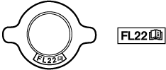
• If the [FL22] mark is shown on or near the cooling system cap, use Mazda Genuine FL22 coolant.
• FL22 type coolant is shipped as a diluted solution. Use the solution as is when replacing coolant.
-
Coolant total amount (reference)
-
4.3 L
Coolant draining procedure
Replacement part
|
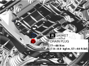
Gasket
Quantity: 2
Location of use: Drain plug
|
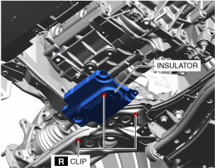
Clip
Quantity: 3
Location of use: Insulator
|
1. Load the vehicle on the auto lift so that it can be lifted up.
2. Remove the seal cover. (See SEAL COVER REMOVAL/INSTALLATION.)
3. Remove the cooling system cap.
4. Remove front under cover No.2. (See FRONT UNDER COVER No.2 REMOVAL/INSTALLATION.)
5. Remove the clips and remove the insulator shown in the figure.
6. Remove the electric motor drain plug and drain the coolant.
7. After completely draining the coolant, tighten the drain plug.
Coolant Replenishment Procedure
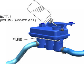
1. Using a commercially-available bottle (volume: approx. 0.5 L), add coolant to the F line on the coolant reserve tank.
-
Note
-
• To prevent air infiltration, add approx. 0.5 L for 1 min.
2. After adding coolant to the F line on the coolant reserve tank, add an additional 0.26 L.
3. Install the cooling system cap and implement air bleeding in the coolant passage. (See Air Bleeding Procedure.)
Air Bleeding Procedure
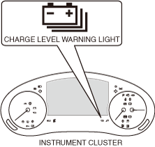
1. Verify that the remaining charge level warning light is not turned on.
-
• If it is turned on, charge the battery.
2. Switch to air bleeding mode using the following procedures.
-
Caution
-
• Verify that the coolant level in the coolant reserve tank changes and that the coolant is flowing while in air bleeding mode.
• If the coolant does not flow, repeat air bleeding mode until the coolant flows.
-
Note
-
• While in air bleeding mode, the electric water pump operates intermittently after operating continuously.
• Under the following conditions, air bleeding mode ends and the water pump returns to normal control.
-
― Main power is switched OFF
-
― Position other than P is shifted
-
― 15 min have elapsed
- (1) Switch the main power ON (READY off).
-
- (2) Perform the following procedure within 60 s.
-
- 1) Release and depress the accelerator pedal 5 times.
-
- 2) Release and depress the brake pedal 10 times.
-
- (3) Switch the main power ON (READY on).
-
3. Listen to the water pump operation sound and vibration sound, and then verify that the water pump transitions to air bleeding mode.
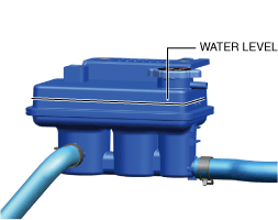
4. Verify the water level in the coolant reserve tank and if the water level is less than the L level, add coolant to the F level.
-
Note
-
• The status of the air bleeding can be determined by the water level in the coolant reserve tank.
Water level at initial stage of air bleeding:
-
― The water pump is operating, but the water flow is weak or there is no water flow.
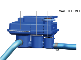
Water level from after several minutes to within 10 min:
-
5. Verify that PCM DTC P2B2A:00 is not stored after 15 min have elapsed from transitioning to air bleeding mode.
-
• If PCM DTC P2B2A:00 is stored, repeat the procedure from Step 2 to Step 5.
6. Main power is switched OFF.
7. Inspect to confirm that there is no coolant leakage at any part. (See COOLANT LEAKAGE INSPECTION.)
8. Install the insulator.
9. Install front under cover No.2. (See FRONT UNDER COVER No.2 REMOVAL/INSTALLATION.)
10. Lower the vehicle to the ground and adjust the coolant amount to the F line on the coolant reserve tank.
11. Install the seal cover. (See SEAL COVER REMOVAL/INSTALLATION.)