 |
ac30zw00003438
FRONT LOWER ARM REMOVAL/INSTALLATION
id021300700600
LH
1. Disconnect the negative battery terminal and wait for 1 min or more. (See NEGATIVE BATTERY TERMINAL DISCONNECTION/CONNECTION.)
2. Remove the wheel and tire. (See WHEEL AND TIRE REMOVAL/INSTALLATION.)
3. Remove the front under cover No.2. (See FRONT UNDER COVER No.2 REMOVAL/INSTALLATION.)
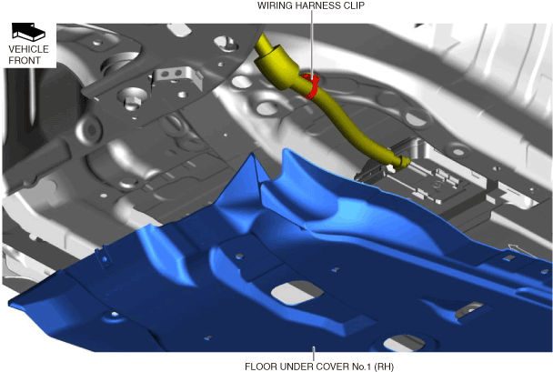
4. Remove the front under cover No.1. (See FRONT UNDER COVER No.1 REMOVAL/INSTALLATION.)
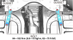
5. Remove the gusset.
ac30zw00003438
|
6. Remove the tunnel cover. (See EXHAUST SYSTEM REMOVAL/INSTALLATION [SKYACTIV-G 2.0].)
7. Remove the front deflector. (See DEFLECTOR REMOVAL/INSTALLATION.)
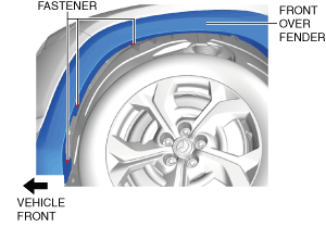
8. Remove the fastener shown in the figure and slightly bend back the front over fender.
a30zzw00005826
|
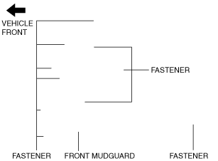
9. Remove the fastener shown in the figure and slightly bend back the front mudguard.
a30zzw00005827
|
10. Remove the front splash shield. (See SPLASH SHIELD REMOVAL/INSTALLATION.)
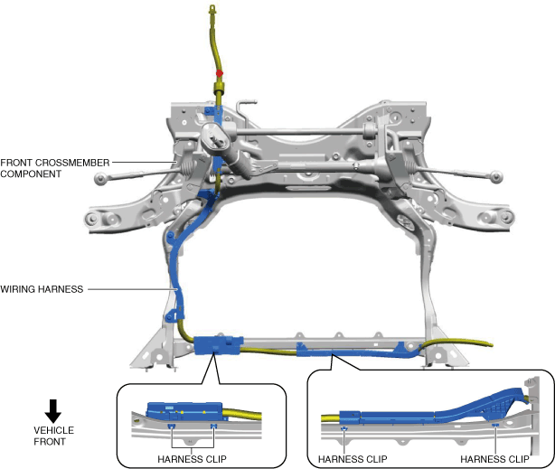
11. Disconnect the harness clips shown in the figure.
a30zzw00005828
|
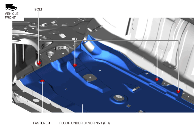
12. Remove the bolts and fastener shown in the figure.
a30zzw00005829
|
13. Detach the wiring harness clip shown in the figure.
a30zzw00005830
|
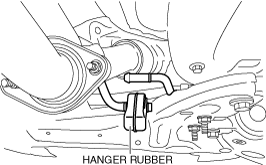
14. Disconnect the hanger rubber from the front crossmember and set it aside.
am3zzw00036468
|
15. Remove the joint cover. (See INTERMEDIATE SHAFT REMOVAL/INSTALLATION.)
16. Disconnect the intermediate shaft (lower side) from the steering gear and linkage. (See INTERMEDIATE SHAFT REMOVAL/INSTALLATION.)
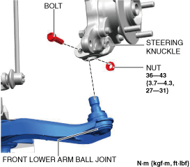
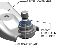
17. Disconnect the front lower arm ball joint from the steering knuckle. (See Front Lower Arm Ball Joint Installation Note.)
a30zzw00005831
|
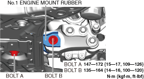
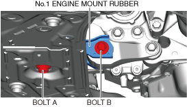
18. Loosen bolt A shown in the figure.
am3zzw00031428
|
19. Remove bolt B shown in the figure. (See No.1 Engine Mount Rubber Installation Note)
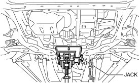
20. Support the front crossmember component using a jack.
ac8wzw00001912
|
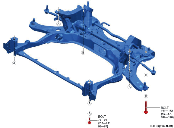
21. Loosen the installation bolts of the front crossmember component.
a30zzw00005832
|
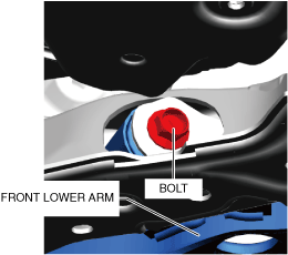
22. Lower the front crossmember assembly approx. 30 mm to the position where the front lower arm installation bolt can be removed.
am3zzw00036466
|
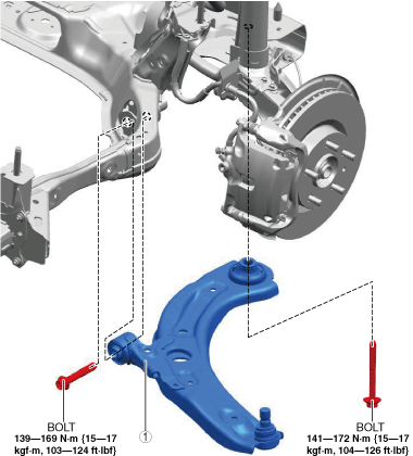
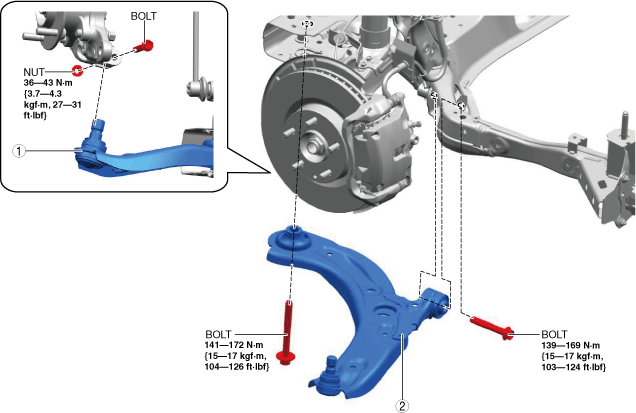
23. Remove in the order shown in the figure.
24. Install in the reverse order of removal. (See Suspension Links Installation Note.)
25. If the front lower arm is replaced, inspect the wheel alignment and adjust it if necessary. (See FRONT WHEEL ALIGNMENT.)
a30zzw00005833
|
|
1
|
Front lower arm
|
No.1 Engine Mount Rubber Installation Note
1. Temporarily tighten bolt A shown in the figure.
a30zzw00005834
|
2. Temporarily tighten bolt B shown in the figure.
3. Tighten bolt A.
4. Tighten bolt B.
RH
1. Remove the wheel and tire. (See WHEEL AND TIRE REMOVAL/INSTALLATION.)
2. Remove the front under cover No.2. (See FRONT UNDER COVER No.2 REMOVAL/INSTALLATION.)
3. Remove in the order shown in the figure.
4. Install in the reverse order of removal. (See Suspension Links Installation Note.)
5. If the front lower arm is replaced, inspect the wheel alignment and adjust it if necessary. (See FRONT WHEEL ALIGNMENT.)
a30zzw00005835
|
|
1
|
Front lower arm ball joint
|
|
2
|
Front lower arm
|
Suspension Links Installation Note
1. When installing the joint section with a rubber bushing, perform the following steps.
Front Lower Arm Ball Joint Installation Note
a30zzw00005836
|
1. Insert the bolt from the front of the vehicle and tighten the nut to the specified torque.