SELECTOR LEVER
id052200701000
Outline
• The selector lever detects the driver’s selector lever operation by the shift position sensor in the selector lever and sends a selector lever operation position signal to the PCM via CAN communication.
• A shift pattern has been adopted for the purpose of preventing driver misoperation and improving safety.
Construction
• A shift-by-wire system has been adopted which connects the selector lever and the transaxle by electrical signals and an actuator instead of shift cables.
• The shift position sensor*1, shift lock sensor, and the shift lock solenoid are built into the selector lever. *1
:Two shift position sensors, a main and a sub, are built into the selector lever to perform detection as a dual system.
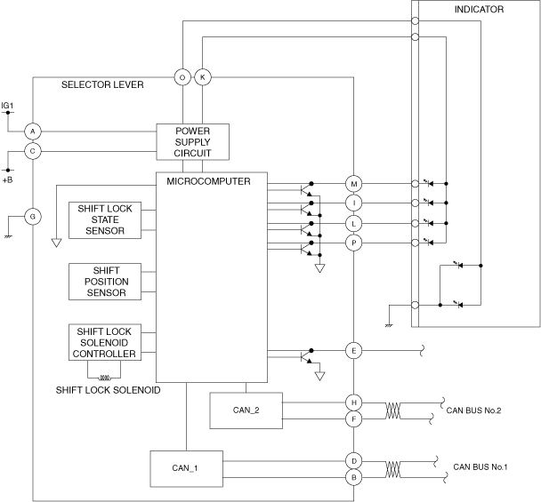
System Wiring Diagram
Block diagram
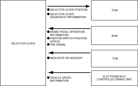
Function
• The selector lever detects the driver’s selector lever operation and sends a signal to the PCM as shift position information.
• The shift lock function inhibits the selector lever from being operated from P to any other shift position when the ignition is switched ON (engine on) and the brake pedal is not depressed. (See
SHIFT-LOCK SYSTEM.)
• The selector lever supplies power to the shift indicator and performs illumination control. For details, refer to the [INDICATOR] item. (See
INDICATOR.)
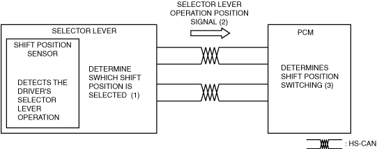
Operation
Operation diagram
Selector lever operation position detection and determination
-
• The shift position sensor in the selector lever detects the driver’s selector lever operation and the microcomputer in the selector lever determines (1) which selector lever position is selected.
• The selector lever sends the determined shift position information (2) to the PCM via CAN communication. The sent signal is used to determine the shift position switching. (See
SHIFT BY WIRE SYSTEM.)