STEERING GEAR AND LINKAGE INSPECTION
id061300700900
1. Remove the steering gear and linkage from the front crossmember component. (See STEERING GEAR AND LINKAGE REMOVAL/INSTALLATION.)
2. Remove the locknuts, tie-rod ends, boot clamps, boot bands, and boots from the steering gear and linkage. (See STEERING GEAR AND LINKAGE DISASSEMBLY.)
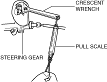
3. Measure the pinion shaft rotation torque using a crescent wrench and pull scale. (Measurement speed reference: 5 rpm)
- (1) Install the crescent wrench to the steering gear.
-
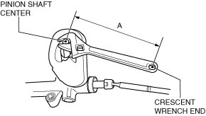
- (2) Measure the distance between the pinion shaft center and the crescent wrench end (point of action of pull scale) shown in the figure and designate this value as A.
-
- (3) For the measurement using a crescent wrench, calculate the pinion shaft rotation torque by the following formula.
- Pinion shaft rotation torque (N·m {kgf·cm, in·lbf}) = Pull scale reading (N {kgf, lbf}) x A (m {cm, in})
-
Pinion shaft rotation torque (pinion rotation angle of ±180° from rack center position)
-
1.0—1.6 N·m {11—16 kgf·cm, 8.9—14 in·lbf}
-