49 JP02 001
Adjustable wrench

STEERING GEAR AND LINKAGE DISASSEMBLY
id061300701000
Special service tool (SST)
|
49 JP02 001
Adjustable wrench
|
|
1. Disconnect the negative battery terminal and wait for 1 min or more. (See NEGATIVE BATTERY TERMINAL DISCONNECTION/CONNECTION.)
2. Remove the wheel and tire. (See WHEEL AND TIRE REMOVAL/INSTALLATION.)
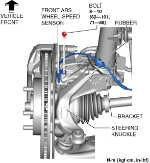
3. Disconnect the rubber from the bracket.
a30zzw00005881
|
4. Disconnect the front ABS wheel-speed sensor wiring harness on the steering knuckle and set it aside so that it does not interfere with the servicing.
5. Remove the tunnel cover. (See EXHAUST SYSTEM REMOVAL/INSTALLATION [SKYACTIV-G 2.0].)
6. Remove the following parts.
7. Remove the front deflector. (See DEFLECTOR REMOVAL/INSTALLATION.)
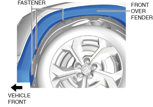
8. Remove the fastener shown in the figure and slightly bend back the front over fender.
a30zzw00005882
|
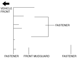
9. Remove the fastener shown in the figure and slightly bend back the front mudguard.
a30zzw00005883
|
10. Remove the front splash shield. (See SPLASH SHIELD REMOVAL/INSTALLATION.)
11. Disconnect the tie-rod end from the steering knuckle. (See TIE-ROD END REMOVAL/INSTALLATION.)
12. Disconnect the front lower arm ball joint from the steering knuckle. (See FRONT LOWER ARM REMOVAL/INSTALLATION.)
13. Remove the floor under cover No.1. (See FLOOR UNDER COVER REMOVAL/INSTALLATION.)
14. Remove the joint cover. (See INTERMEDIATE SHAFT REMOVAL/INSTALLATION.)
15. Disconnect the intermediate shaft (lower side) from the steering gear and linkage. (See INTERMEDIATE SHAFT REMOVAL/INSTALLATION.)
16. Disconnect the ground plate. (See GROUND PLATE DISCONNECTION/CONNECTION.)
17. Remove the front crossmember component. (See FRONT CROSSMEMBER REMOVAL/INSTALLATION.)
18. Remove the hole cover No.1 and hole cover No.2. (See FRONT CROSSMEMBER REMOVAL/INSTALLATION.)
19. Remove the steering gear and linkage from the front crossmember component. (See STEERING GEAR AND LINKAGE REMOVAL/INSTALLATION.)
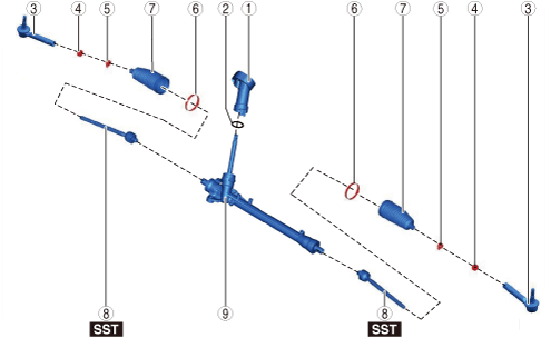
20. Disassemble in the order shown in the figure.
a30jjw00001042
|
|
1
|
Dust cover
|
|
2
|
O-ring
|
|
3
|
Tie-rod end
(See Tie-rod End Disassembly Note.)
|
|
4
|
Locknut
|
|
5
|
Boot clamp
|
|
6
|
Boot band
(See Boot Band Disassembly Note.)
|
|
7
|
Boot
|
|
8
|
Tie rod
(See Tie Rod Disassembly Note.)
|
|
9
|
Steering gear
|
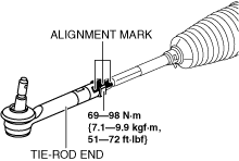
Tie-rod End Disassembly Note
1. Place alignment marks as shown in the figure for reference in assembly.
ac30zw00001995
|
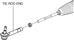
2. Remove the tie-rod end.
ac30zw00001996
|
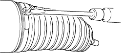
Boot Band Disassembly Note
1. Insert a flathead screwdriver into the crimped part of the boot clamp, expand the crimped part, and then remove the boot clamp as shown in the figure.
ac5wzw00001035
|
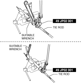
Tie Rod Disassembly Note
1. Lock the steering gear against rotation using a wrench and remove the tie rod using the SST.
am3zzw00033061
|