 |
a30zzw00005876
STEERING GEAR AND LINKAGE REMOVAL/INSTALLATION
id061300700800
1. Disconnect the negative battery terminal and wait for 1 min or more. (See NEGATIVE BATTERY TERMINAL DISCONNECTION/CONNECTION.)
2. Remove the wheel and tire. (See WHEEL AND TIRE REMOVAL/INSTALLATION.)
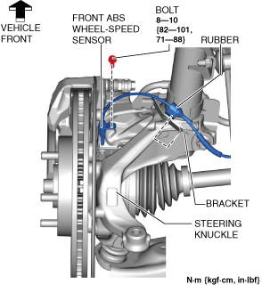
3. Disconnect the rubber from the bracket.
a30zzw00005876
|
4. Disconnect the front ABS wheel-speed sensor wiring harness on the steering knuckle and set it aside so that it does not interfere with the servicing.
5. Remove the tunnel cover. (See EXHAUST SYSTEM REMOVAL/INSTALLATION [SKYACTIV-G 2.0].)
6. Remove the following parts.
7. Remove the front deflector. (See DEFLECTOR REMOVAL/INSTALLATION.)
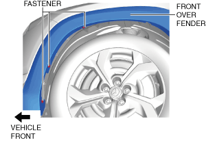
8. Remove the fastener shown in the figure and slightly bend back the front over fender.
a30zzw00005877
|
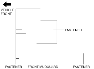
9. Remove the fastener shown in the figure and slightly bend back the front mudguard.
a30zzw00005878
|
10. Remove the front splash shield. (See SPLASH SHIELD REMOVAL/INSTALLATION.)
11. Disconnect the tie-rod end from the steering knuckle. (See TIE-ROD END REMOVAL/INSTALLATION.)
12. Disconnect the front lower arm ball joint from the steering knuckle. (See FRONT LOWER ARM REMOVAL/INSTALLATION.)
13. Remove the floor under cover No.1. (See FLOOR UNDER COVER REMOVAL/INSTALLATION.)
14. Remove the joint cover. (See INTERMEDIATE SHAFT REMOVAL/INSTALLATION.)
15. Disconnect the intermediate shaft (lower side) from the steering gear and linkage. (See INTERMEDIATE SHAFT REMOVAL/INSTALLATION.)
16. Disconnect the ground plate. (See GROUND PLATE DISCONNECTION/CONNECTION.)
17. Remove the front crossmember component. (See FRONT CROSSMEMBER REMOVAL/INSTALLATION.)
18. Remove the hole cover No.1 and hole cover No.2. (See FRONT CROSSMEMBER REMOVAL/INSTALLATION.)
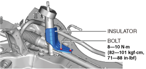
19. Remove the Insulator. (See Insulator Installation Note.)
ac30zw00000536
|
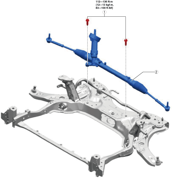
20. Remove in the order shown in the figure.
21. Install in the reverse order of removal.
22. After installation, inspect the front wheel alignment. (See FRONT WHEEL ALIGNMENT.)
a30zzw00005879
|
|
1
|
Steering gear and linkage installation bolt
|
|
2
|
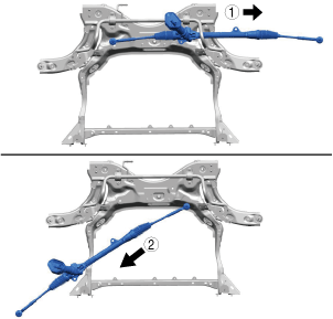
Steering gear and linkage
|
Steering Gear and Linkage Removal Note
1. Move the steering gear and linkage in the direction of the arrow in the order shown in the figure and remove it.
a30jjw00001040
|
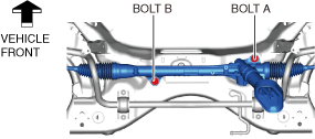
Steering Gear and Linkage Installation Bolt Installation Note
1. Temporarily tighten the steering gear and linkage installation bolts.
a30zzw00005880
|
2. Tighten bolt A.
3. Tighten bolt B.
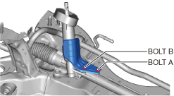
Insulator Installation Note
1. Temporarily tighten bolt A.
ac30zw00000542
|
2. Tighten bolt B.
3. Tighten bolt A.