 |
a30zzw00006394
AIRFLOW MODE ACTUATOR INSPECTION
id074000701600
Actuator inspection
1. Disconnect the negative battery terminal. (See NEGATIVE BATTERY TERMINAL DISCONNECTION/CONNECTION.)
2. Remove the airflow mode actuator. (See AIRFLOW MODE ACTUATOR REMOVAL.)(See AIRFLOW MODE ACTUATOR INSTALLATION.)
3. Connect the mode actuator connector.
4. Connect the negative battery terminal. (See NEGATIVE BATTERY TERMINAL DISCONNECTION/CONNECTION.)
5. Switch the ignition ON (engine off or on).
6. Connect the M-MDS to the DLC-2.
7. Operate the airflow mode actuator using the simulation function [MODE_ACTAT_MODE] of the dash-electrical supply unit. (See SIMULATION INSPECTION.)(See SIMULATION TABLE [DASH-ELECTRICAL SUPPLY UNIT].)
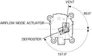
8. Verify that the mode actuator operation condition is as shown in the figure.
a30zzw00006394
|
9. If it cannot be operated, replace the mode actuator. (See AIRFLOW MODE ACTUATOR REMOVAL.)(See AIRFLOW MODE ACTUATOR INSTALLATION.)
Position sensor inspection
1. Connect the M-MDS to the DLC-2.
2. Switch the ignition ON (engine on).
3. Display PID [MODE_ACTAT_POS] using the M-MDS. (See PID/DATA MONITOR INSPECTION.)(See PID/DATA MONITOR TABLE [DASH-ELECTRICAL SUPPLY UNIT].)
4. Operate the mode switch.
5. Verify that the PID value switches according to the mode switch operation.
6. If the PID value does not switch, replace the mode actuator. (See AIRFLOW MODE ACTUATOR REMOVAL.)(See AIRFLOW MODE ACTUATOR INSTALLATION.)