Note
FRONT OUTER HANDLE REMOVAL/INSTALLATION
id091400200300
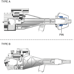
TYPE A
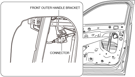
Driver's Side
1. Fully close the front door glass.
2. Disconnect the negative battery terminal. (See NEGATIVE BATTERY TERMINAL DISCONNECTION/CONNECTION.)
3. Remove the following parts.
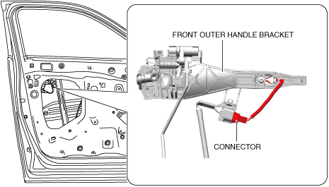
4. Disconnect the connectors. (With advanced keyless entry system)
a30zzw00006303
|
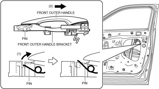
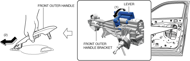
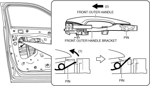
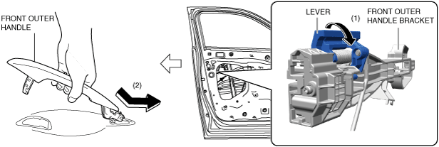
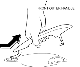
5. While pressing the front outer handle bracket pin in the direction of arrow (1) shown in the figure, pull the front outer handle in the direction of arrow (2), and detach the front outer handle bracket pin from the front outer handle.
a30zzw00006304
|
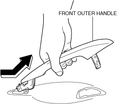
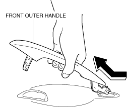
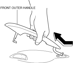
6. Remove the front outer handle in the direction of the arrow shown in the figure. (See Front outer handle installation note.)
a30zzw00006305
|
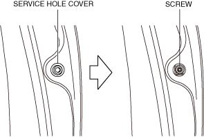
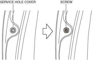
7. Remove the service hole cover.
a30zzw00006306
|
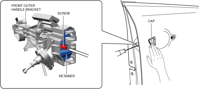
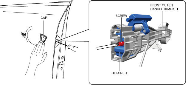
8. Loosen the screw.
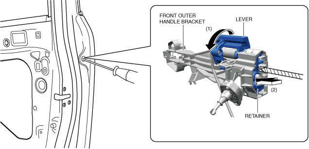
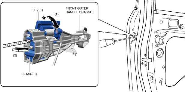
9. While moving the lever in the direction of arrow (1) shown in the figure, push the retainer in the direction of arrow (2) using a tape-wrapped screwdriver, and then secure the lever.
a30zzw00006307
|
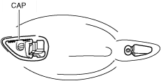
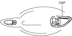
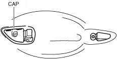
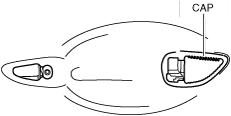
10. Remove the cap. (See Cap installation note.)
a30zzw00006308
|
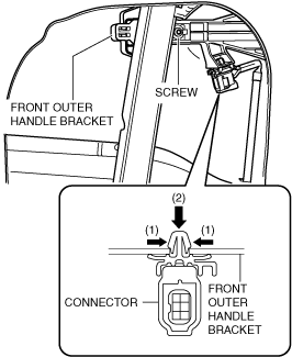
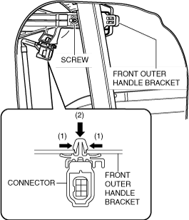
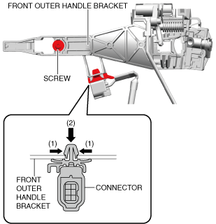
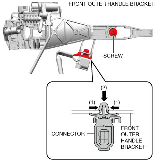
11. While pressing the tabs of the clip in the direction of arrows (1) shown in the figure, pull the connector in the direction of arrow (2) to detach it from the front outer handle bracket. (With advanced keyless entry system)
a30zzw00006309
|
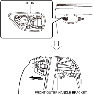
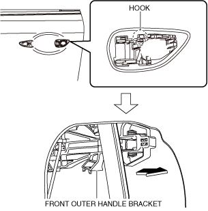
12. Loosen the screw.
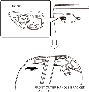
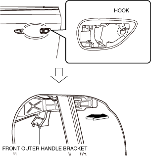
13. Pull the front outer handle bracket in the direction of the arrow shown in the figure and detach the front outer handle bracket hook from the body.
a30zzw00006310
|
14. Remove the front outer handle bracket and front door key cylinder as a single unit.
15. Remove the front door key cylinder. (See FRONT DOOR KEY CYLINDER REMOVAL/INSTALLATION.)
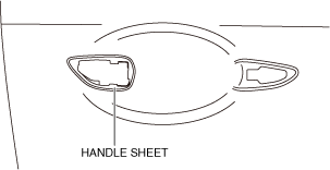
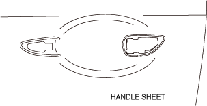
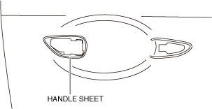
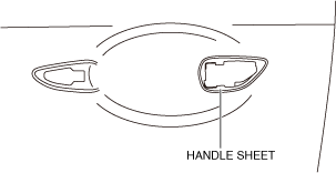
16. Remove the handle sheet.
a30zzw00006311
|
17. Install in the reverse order of removal.
Cap installation note
1. Tighten the screw while holding the cap, and return the retainer to its original position.
a30zzw00006312
|
Front outer handle installation note
1. While holding the front outer handle bracket, move the lever in the direction of arrow (1) shown in the figure, and attach the front outer handle in the direction of arrow (2).
a30zzw00006313
|
Passenger's Side
1. Fully close the front door glass.
2. Disconnect the negative battery terminal. (See NEGATIVE BATTERY TERMINAL DISCONNECTION/CONNECTION.)
3. Remove the following parts.
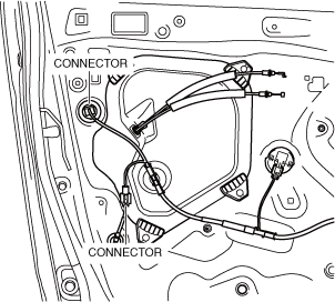
4. Disconnect the connectors.
a30zzw00006314
|
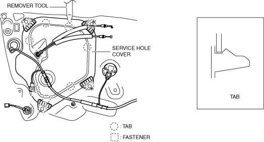
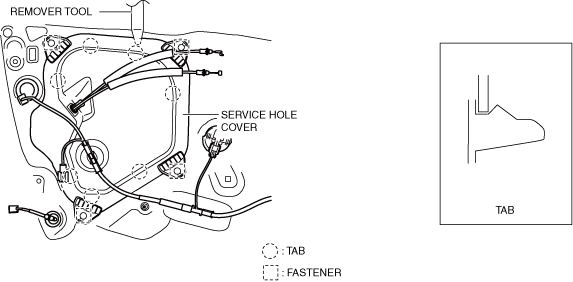
5. Remove the fasteners.
a30zzw00006315
|
6. Detach the service hole cover tabs from the body using a remover tool.
7. Remove the clips.
a30zzw00006316
|
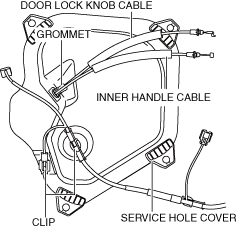
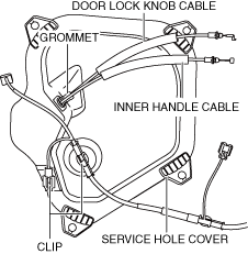
8. Remove the grommet.
9. Disconnect the door lock knob cable and inner handle cable from the service hole cover.
10. Remove the service hole cover. (See Service hole cover installation note.)
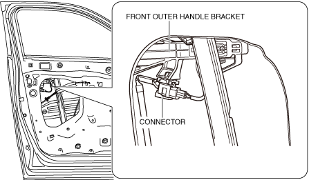
11. Disconnect the connectors. (With advanced keyless entry system)
a30zzw00006317
|
12. While pulling the front outer handle bracket pin in the direction of arrow (1) shown in the figure, pull the front outer handle in the direction of arrow (2) and detach the front outer handle bracket pin from the front outer handle.
a30zzw00006318
|
13. Remove the front outer handle in the direction of the arrow shown in the figure. (See Front outer handle installation note.)
a30zzw00006319
|
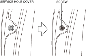
14. Remove the service hole cover.
a30zzw00006320
|
15. Loosen the screw.
16. While moving the lever in the direction of arrow (1) shown in the figure, push the retainer in the direction of arrow (2) using a tape-wrapped screwdriver, and then secure the lever.
a30zzw00006321
|
17. Remove the cap. (See Cap installation note.)
a30zzw00006322
|
18. While pressing the tabs of the clip in the direction of arrows (1) shown in the figure, pull the connector in the direction of arrow (2) to detach it from the front outer handle bracket. (With advanced keyless entry system)
a30zzw00006323
|
19. Loosen the screw.
20. Pull the front outer handle bracket in the direction of the arrow shown in the figure and detach the front outer handle bracket hooks from the body.
a30zzw00006324
|
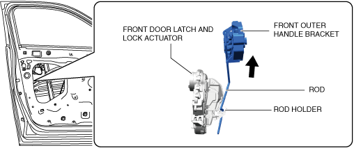
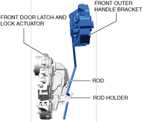
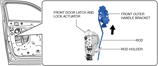
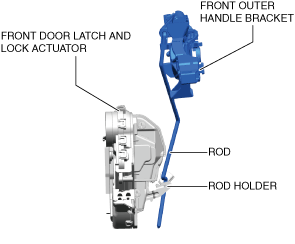
21. Lift the front outer handle bracket in the direction of the arrow shown in the figure and pull out the rod from the rod holder. (See Front outer handle bracket installation note.)
a30zzw00006325
|
22. Remove the front outer handle bracket.
23. Remove the handle sheet.
a30zzw00006326
|
24. Install in the reverse order of removal.
Cap installation note
1. Tighten the screw while holding the cap, and return the retainer to its original position.
a30zzw00006327
|
Front outer handle installation note
1. While holding the front outer handle bracket, move the lever in the direction of arrow (1) as shown in the figure, and attach the front outer handle in the direction of arrow (2).
a30zzw00006328
|
Front outer handle bracket installation note
1. Move the rod back and forth and verify that it is inserted into the rod holder hole.
a30zzw00006329
|
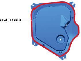
Service hole cover installation note
1. When installing the service hole cover, verify that the seal rubber is not wet.
a30zzw00006330
|
TYPE B
Driver's side
1. Fully close the front door glass.
2. Disconnect the negative battery terminal. (See NEGATIVE BATTERY TERMINAL DISCONNECTION/CONNECTION.)
3. Remove the following parts.
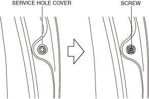
4. Remove the service hole cover.
a30zzw00007452
|
5. Loosen the screw.
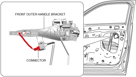
6. Disconnect the connectors. (With advanced keyless entry system)
a30zzw00007453
|
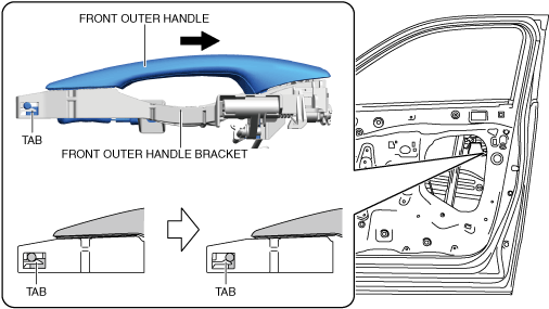
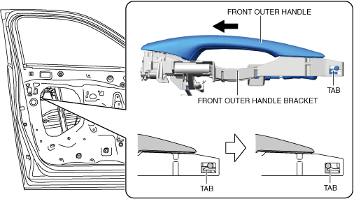
7. Pull the front outer handle in the direction of the arrow shown in the figure, and detach the front outer handle bracket tab from the front outer handle.
a30zzw00007454
|
8. Remove the front outer handle in the direction of the arrow shown in the figure.
a30zzw00007455
|
9. Remove the cap.
a30zzw00007456
|
10. While pressing the tabs of the clip in the direction of arrows (1) shown in the figure, pull the connector in the direction of arrow (2) to detach it from the front outer handle bracket. (With advanced keyless entry system)
a30zzw00007457
|
11. Loosen the screw.
12. Pull the front outer handle bracket in the direction of the arrow shown in the figure and detach the front outer handle bracket hook from the body.
a30zzw00007458
|
13. Remove the front outer handle bracket and front door key cylinder as a single unit.
14. Remove the front door key cylinder. (See FRONT DOOR KEY CYLINDER REMOVAL/INSTALLATION.)
15. Remove the handle sheet.
a30zzw00007459
|
16. Install in the reverse order of removal.
Passenger's Side
1. Passenger's Side
2. Disconnect the negative battery terminal. (See NEGATIVE BATTERY TERMINAL DISCONNECTION/CONNECTION.)
3. Remove the following parts.
4. Disconnect the connectors.
a30zzw00007460
|
5. Remove the fasteners.
a30zzw00007461
|
6. Detach the service hole cover tabs from the body using a remover tool.
7. Remove the clips.
a30zzw00007462
|
8. Remove the grommet.
9. Disconnect the door lock knob cable and inner handle cable from the service hole cover.
10. Remove the service hole cover. (See Service hole cover installation note.)
11. Remove the service hole cover.
a30zzw00007463
|
12. Loosen the screw.
13. Disconnect the connectors. (With advanced keyless entry system)
a30zzw00007464
|
14. Pull the front outer handle in the direction of the arrow shown in the figure, and detach the front outer handle bracket tab from the front outer handle.
a30zzw00007465
|
15. Remove the front outer handle in the direction of the arrow shown in the figure.
a30zzw00007466
|
16. Remove the cap.
a30zzw00007467
|
17. While pressing the tabs of the clip in the direction of arrows (1) shown in the figure, pull the connector in the direction of arrow (2) to detach it from the front outer handle bracket. (With advanced keyless entry system)
a30zzw00007468
|
18. Loosen the screw.
19. Pull the front outer handle bracket in the direction of the arrow shown in the figure and detach the front outer handle bracket hooks from the body.
a30zzw00007469
|
20. Lift the front outer handle bracket in the direction of the arrow shown in the figure and pull out the rod from the rod holder. (See Front outer handle bracket installation note.)
a30zzw00007470
|
21. Remove the front outer handle bracket.
22. Remove the handle sheet.
a30zzw00007471
|
23. Install in the reverse order of removal.
Front outer handle bracket installation note
1. Move the rod back and forth and verify that it is inserted into the rod holder hole.
a30zzw00007472
|
Service hole cover installation note
1. When installing the service hole cover, verify that the seal rubber is not wet.
a30zzw00007473
|