Diagnostic procedure
|
STEP
|
INSPECTION
|
ACTION
|
|
|---|---|---|---|
|
1
|
VERIFY FREEZE FRAME DATA AND DIAGNOSTIC MONITORING TEST RESULTS HAVE BEEN RECORDED
• Have FREEZE FRAME DATA been recorded?
|
Yes
|
Go to the next step.
|
|
No
|
Record the FREEZE FRAME DATA on the repair order, then go to the next step.
|
||
|
2
|
VERIFY RELATED SERVICE INFORMATION AVAILABILITY
• Verify related Service Information availability.
• Is any related Service Information available?
|
Yes
|
Perform repair or diagnosis according to the available Service Information.
• If the vehicle is not repaired, go to the next step.
|
|
No
|
Go to the next step.
|
||
|
3
|
VERIFY RELATED PENDING AND STORED DTC
• Turn the ignition switch off, then to the ON position. (Engine off)
• Verify pending and stored DTCs using the M-MDS.
• Is other DTC present?
|
Yes
|
Go to the appropriate DTC troubleshooting procedures.
|
|
No
|
Go to the next step.
|
||
|
4
|
IDENTIFY TRIGGER DTC FOR FREEZE FRAME DATA
• Is DTC P0134 on FREEZE FRAME DATA?
|
Yes
|
Go to the next step.
|
|
No
|
Go to troubleshooting procedures for DTC on FREEZE FRAME DATA.
(See DTC TABLE [L8, LF].)
|
||
|
5
|
INSPECT INSTALLATION OF A/F SENSOR
• Inspect if the A/F sensor is loosely installed.
• Is the sensor installed securely?
|
Yes
|
Go to the next step.
|
|
No
|
Install sensor securely, then go to Step 10.
|
||
|
6
|
INSPECT A/F SENSOR HEATER
• Inspect the A/F sensor heater.
• Is the A/F sensor heater normal?
|
Yes
|
Go to the next step.
|
|
No
|
Replace the A/F sensor, then go to Step 10.
|
||
|
7
|
INSPECT A/F SENSOR
• Inspect the A/F sensor.
• Is there any malfunction?
|
Yes
|
Go to the next step.
|
|
No
|
Replace the A/F sensor, then go to Step 10.
|
||
|
8
|
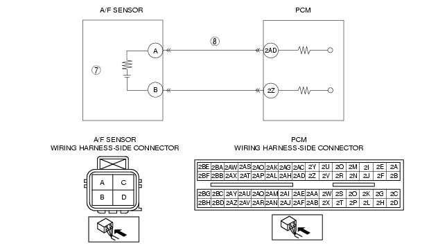
INSPECT A/F SENSOR SIGNAL CIRCUIT FOR SHORT TO POWER SUPPLY CIRCUIT
• Turn the ignition switch to OFF.
• Disconnect the A/F sensor connector.
• Measure the voltage between A/F sensor terminal A (wiring harness-side) and GND.
• Is the voltage above 3.22 V?
|
Yes
|
Repair or replace for short to power supply circuit, then go to Step 10.
|
|
No
|
Go to the next step.
|
||
|
9
|
INSPECT A/F SENSOR SIGNAL CIRCUIT FOR OPEN
• Disconnect the PCM connector.
• Inspect for continuity between PCM terminal 2AD (wiring harness-side) and A/F sensor terminal A (wiring harness-side).
• Is there continuity?
|
Yes
|
Go to the next step.
|
|
No
|
Repair or replace for open circuit, then go to the net step.
|
||
|
10
|
VERIFY TROUBLESHOOTING OF DTC P0134 COMPLETED
• Make sure to reconnect all disconnected connectors.
• Turn the ignition switch to the ON position. (Engine off)
• Clear the DTC from memory using the M-MDS.
• Perform the KOER self-test.
(See KOEO/KOER SELF TEST [L8, LF].)
• Is the PENDING CODE for this DTC present?
|
Yes
|
Replace the PCM, then go to the next step.
|
|
No
|
Go to the next step.
|
||
|
11
|
VERIFY AFTER REPAIR PROCEDURE
• Perform the "AFTER REPAIR PROCEDURE".
• Are any DTC present?
|
Yes
|
Go to the applicable DTC troubleshooting.
(See DTC TABLE [L8, LF].)
|
|
No
|
Troubleshooting completed.
|
||