Diagnostic procedure
|
STEP
|
INSPECTION
|
ACTION
|
|
|---|---|---|---|
|
1
|
VERIFY FREEZE FRAME DATA HAS BEEN RECORDED
• Has the FREEZE FRAME DATA been recorded?
|
Yes
|
Go to the next step.
|
|
No
|
Record the FREEZE FRAME DATA on the repair order, then go to the next step.
|
||
|
2
|
VERIFY RELATED REPAIR INFORMATION AVAILABILITY
• Verify related Service Bulletins and/or on-line repair information availability.
• Is any related repair information available?
|
Yes
|
Perform repair or diagnosis according to the available repair information.
• If the vehicle is not repaired, go to the next step.
|
|
No
|
Go to the next step.
|
||
|
3
|
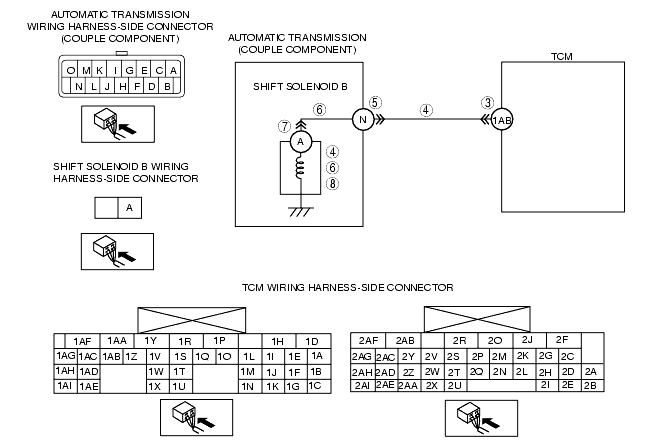
INSPECT TCM CONNECTOR FOR POOR CONNECTION
• Turn the ignition switch to the LOCK position.
• Disconnect the TCM connector.
• Inspect for poor connection at TCM terminal 1AB (such as damaged/pulled-out pins, corrosion).
• Is terminal normal?
|
Yes
|
Go to the next step.
|
|
No
|
Repair or replace the connector and/or terminal, then go to Step 9.
|
||
|
4
|
INSPECT RESISTANCE OF SHIFT SOLENOID B CIRCUIT
• Inspect for resistance between TCM terminal 1AB (wiring harness-side) and body ground.
• Is the resistance within 5.0-5.6 ohms?
|
Yes
|
Go to Step 9.
|
|
No
|
Go to the next step.
|
||
|
5
|
INSPECT COUPLE COMPONENT CONNECTOR FOR POOR CONNECTION
• Turn the ignition switch to the LOCK position.
• Disconnect the couple component connector.
• Inspect for poor connection at couple component terminal N (such as damaged/pulled-out pins, corrosion).
• Is terminal normal?
|
Yes
|
Go to the next step.
|
|
No
|
Repair or replace the connector and/or terminal, then go to Step 9.
|
||
|
6
|
INSPECT RESISTANCE OF SHIFT SOLENOID B CIRCUIT
• Inspect the resistance between couple component (transmission case side) terminal N and body ground.
• Is the resistance within 5.0-5.6 ohms?
|
Yes
|
Go to the next step.
|
|
No
|
Go to Step 9.
|
||
|
7
|
INSPECT SHIFT SOLENOID B CONNECTOR FOR POOR CONNECTION
• Turn the ignition switch to the LOCK position.
• Disconnect the shift solenoid B connector.
• Inspect for poor connection at shift solenoid B terminal A (such as damaged/pulled-out pins, corrosion).
• Is terminal normal?
|
Yes
|
Go to the next step.
|
|
No
|
Repair or replace the connector and/or terminal, then go to Step 9.
|
||
|
8
|
INSPECT SHIFT SOLENOID B
• Inspect the shift solenoid B.
• Is the shift solenoid B normal?
|
Yes
|
Repair or replace the wiring harness (couple component connector-shift solenoid B) for short to ground, then go to the next step.
|
|
No
|
Replace the control valve body, then go to the next step.
|
||
|
9
|
VERIFY TROUBLESHOOTING OF DTC P0976 COMPLETED
• Make sure to reconnect all the disconnected connectors.
• Clear the DTC from the memory using the M-MDS.
• Drive the vehicle in D range and make sure that gears shift smoothly from 1GR to 6GR.
• Is same DTC present?
|
Yes
|
Replace the TCM, then go to the next step.
|
|
No
|
Go to the next step.
|
||
|
10
|
VERIFY AFTER REPAIR PROCEDURE
• Perform the "After Repair Procedure".
• Are any DTCs present?
|
Yes
|
Go to the applicable DTC inspection.
(See DTC TABLE [SJ6A-EL].)
|
|
No
|
Troubleshooting completed.
|
||