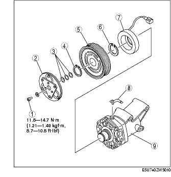
1. Disassemble in the order indicated in the table.
|
1
|
Bolt
|
|
2
|
Pressure plate
|
|
3
|
Shim
(See Shim Installation Note.)
|
|
4
|
Snap ring
|
|
5
|
A/C compressor pulley
|
|
6
|
Snap ring
|
|
7
|
Stator
(See Stator Installation Note.)
|
|
8
|
Clamp
|
|
9
|
A/C compressor body
|
2. Assemble in the reverse order of disassembly.
3. Adjust the magnetic clutch clearance. (See MAGNETIC CLUTCH ADJUSTMENT.)
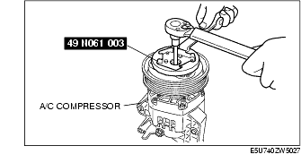
1. When removing or installing the bolt, hold the pressure plate as shown in the figure.
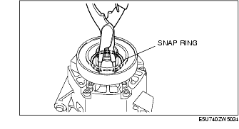
1. Remove the snap ring using a snap ring pliers.
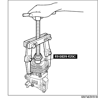
1. Remove the A/C compressor pulley using the SST (49 0839 425C).
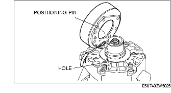
1. Align the positioning pin with the hole of A/C compressor body and insert.
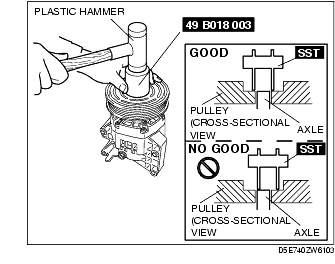
1. Install the inner wheel of the pulley using a plastic hammer and SST (49 B018 003) to the compressor.
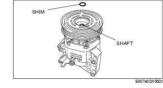
1. First, insert the 1 mm (0.039 in) thick shim into the shaft.