|
1
|
VERIFY FREEZE FRAME DATA (MODE 12) HAS BEEN RECORDED
• Has the FREEZE FRAME DATA (Mode 12) been recorded?
|
Yes
|
Go to the next step.
|
|
No
|
Record the FREEZE FRAME DATA (Mode 12) on the repair order, then go to the next step.
|
|
2
|
VERIFY RELATED SERVICE INFORMATION AVAILABILITY
• Verify related Service Information availability.
• Is any related Service Information available?
|
Yes
|
Perform repair or diagnosis according to the available Service Information.
• If the vehicle is not repaired, go to the next step.
|
|
No
|
Go to the next step.
|
|
3
|
VERIFY WHETHER MALFUNCTION IS OPEN CIRCUIT OR SHORT TO GROUND
• Connect the M-MDS to the DLC-2.
• Perform the PID/DATA Monitor and Record Procedure and access the CPP PID.
• Verify the CPP PID during operating the clutch pedal.
|
Yes
|
Go to Step 13.
|
|
No
|
If the CPP PID is always On:
• Go to the next step.
If the CPP PID is always Off:
• Go to Step 8.
|
|
4
|
INSPECT CPP SWITCH CONNECTOR AND TERMINALS
• Turn the ignition switch off.
• Disconnect the CPP switch connector.
• Inspect for poor connection (such as damaged/pulled-out pins, corrosion).
• Is there any malfunction?
|
Yes
|
Repair or replace the connector or terminals, then go to Step 13.
|
|
No
|
Go to the next step.
|
|
5
|
INSPECT CPP SWITCH
• Inspect the CPP switch.
• Is there any malfunction?
|
Yes
|
Replace the CPP switch, then go to Step 13.
|
|
No
|
Go to the next step.
|
|
6
|
INSPECT CPP SWITCH SIGNAL CIRCUIT FOR SHORT TO GROUND
• CPP switch connector is disconnected.
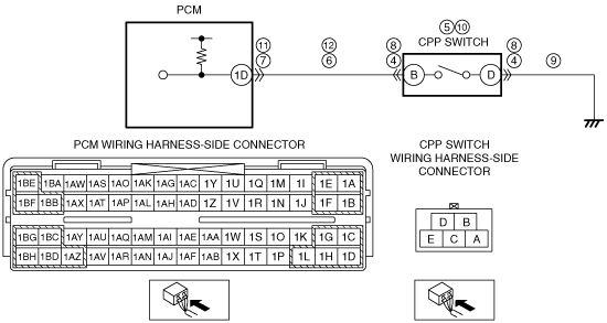
• Inspect for continuity between CPP switch terminal B (wiring harness-side) and body ground.
• Is there continuity?
|
Yes
|
If the short to ground circuit could be detected:
• Repair or replace the wiring harness for a possible short to ground.
If the short to ground circuit could not be detected:
• Replace the PCM (short to ground in PCM internal circuit).
Go to Step 13.
|
|
No
|
Go to the next step.
|
|
7
|
INSPECT PCM CONNECTOR AND TERMINALS
• Disconnect the PCM connector.
• Inspect for poor connection (such as damaged/pulled-out pins, corrosion).
• Is there any malfunction?
|
Yes
|
Repair or replace the connector or terminals, then go to Step 13.
|
|
No
|
Go to Step 13.
|
|
8
|
INSPECT CPP SWITCH CONNECTOR AND TERMINALS
• Turn the ignition switch off.
• Disconnect the CPP switch connector.
• Inspect for poor connection (such as damaged/pulled-out pins, corrosion).
• Is there any malfunction?
|
Yes
|
Repair or replace the connector or terminals, then go to Step 13.
|
|
No
|
Go to the next step.
|
|
9
|
INSPECT CPP SWITCH GROUND CIRCUIT FOR OPEN CIRCUIT
• CPP switch connector is disconnected.
• Inspect for continuity between CPP switch terminal D (wiring harness-side) and body ground.
• Is there continuity?
|
Yes
|
Go to the next step.
|
|
No
|
Repair or replace the wiring harness for a possible open circuit, then go to Step 13.
|
|
10
|
INSPECT CPP SWITCH
• Inspect the CPP switch.
• Is there any malfunction?
|
Yes
|
Replace the CPP switch, then go to Step 13.
|
|
No
|
Go to the next step.
|
|
11
|
INSPECT PCM CONNECTOR AND TERMINALS
• Disconnect the PCM connector.
• Inspect for poor connection (such as damaged/pulled-out pins, corrosion).
• Is there any malfunction?
|
Yes
|
Repair or replace the connector or terminals, then go to Step 13.
|
|
No
|
Go to the next step.
|
|
12
|
INSPECT CPP SWITCH SIGNAL CIRCUIT FOR OPEN CIRCUIT
• CPP switch and PCM connectors are disconnected.
• Inspect for continuity between CPP switch terminal B (wiring harness-side) and PCM terminal 1D (wiring harness-side).
• Is there continuity?
|
Yes
|
Go to the next step.
|
|
No
|
Repair or replace the wiring harness for a possible open circuit, then go to the next step.
|
|
13
|
VERIFY DTC TROUBLESHOOTING COMPLETED
• Make sure to reconnect all disconnected connectors.
• Start the engine and warm it up completely.
• Clear the DTC from the PCM memory using the M-MDS.
• Operate the clutch pedal while the vehicle runs and stops 8 times alternately.
• Perform the Pending Trouble Code Access Procedure.
• Is the PENDING CODE for this DTC present?
|
Yes
|
Replace the PCM, then go to the next step.
|
|
No
|
Go to the next step.
|
|
14
|
VERIFY AFTER REPAIR PROCEDURE
• Perform the “AFTER REPAIR PROCEDURE”.
• Are any DTCs present?
|
Yes
|
Go to the applicable DTC troubleshooting.
|
|
No
|
DTC troubleshooting completed.
|