 |
amxzzw00004060
CYLINDER HEAD GASKET REPLACEMENT [SKYACTIV-G 1.5, SKYACTIV-G 2.0]
id0110h8800700
1. Disconnect the negative battery terminal. (See NEGATIVE BATTERY TERMINAL DISCONNECTION/CONNECTION.)
2. Remove the seal cover. (See SEAL COVER REMOVAL/INSTALLATION [SKYACTIV-G 1.5, SKYACTIV-G 2.0].)
3. Remove the ignition coil/ion sensors. (See IGNITION COIL/ION SENSOR REMOVAL/INSTALLATION [SKYACTIV-G 1.5, SKYACTIV-G 2.0].)
4. Remove the air cleaner, air hose and resonance chamber No.1 as a single unit. (See INTAKE-AIR SYSTEM REMOVAL/INSTALLATION [SKYACTIV-G 1.5, SKYACTIV-G 2.0].)
5. Remove the drive belt. (See DRIVE BELT REMOVAL/INSTALLATION [SKYACTIV-G 1.5, SKYACTIV-G 2.0].)
6. Remove the front crossmember under cover. (See FRONT CROSSMEMBER UNDER COVER REMOVAL/INSTALLATION.)
7. Drain the engine oil. (See ENGINE OIL REPLACEMENT [SKYACTIV-G 1.5, SKYACTIV-G 2.0].)
8. Drain the engine coolant. (See ENGINE COOLANT REPLACEMENT [SKYACTIV-G 1.5, SKYACTIV-G 2.0].)
9. Remove the intake manifold. (See INTAKE-AIR SYSTEM REMOVAL/INSTALLATION [SKYACTIV-G 1.5, SKYACTIV-G 2.0].)
10. Set aside the exhaust manifold to the vehicle rear. (See EXHAUST SYSTEM REMOVAL/INSTALLATION [SKYACTIV-G 1.5, SKYACTIV-G 2.0].)
11. Remove the high pressure fuel pump and rear housing. (See HIGH PRESSURE FUEL PUMP REMOVAL/INSTALLATION [SKYACTIV-G 1.5, SKYACTIV-G 2.0].)
12. Remove the oil pan. (See OIL PAN REMOVAL/INSTALLATION [SKYACTIV-G 1.5, SKYACTIV-G 2.0].)
13. Remove the timing chain and chain guide. (See TIMING CHAIN REMOVAL/INSTALLATION [SKYACTIV-G 1.5, SKYACTIV-G 2.0].)
14. Remove the OCV. (See OIL CONTROL VALVE (OCV) REMOVAL/INSTALLATION [SKYACTIV-G 1.5, SKYACTIV-G 2.0].)
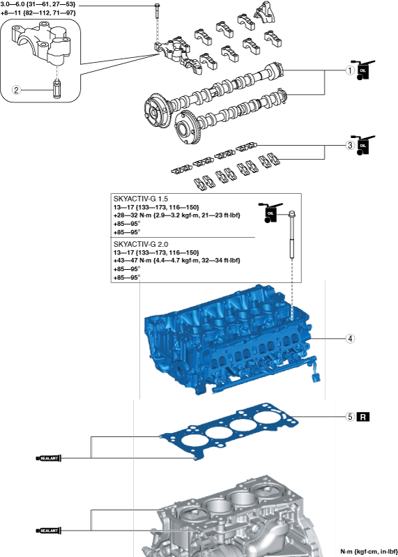
15. Remove in the order indicated in the table.
16. Install in the reverse order of removal.
17. Refill with the specified type and amount of the engine oil. (See ENGINE OIL REPLACEMENT [SKYACTIV-G 1.5, SKYACTIV-G 2.0].)
18. Refill the engine coolant. (See ENGINE COOLANT REPLACEMENT [SKYACTIV-G 1.5, SKYACTIV-G 2.0].)
19. Start the engine, and inspect and adjust the following:
amxzzw00004060
|
|
1
|
Camshaft
(See Camshaft Removal Note.)
(See Camshaft Installation Note.)
|
|
2
|
OCV oil filter
|
|
3
|
Rocker arm
(See Rocker Arm Removal Note.)
(See Rocker Arm Installation Note.)
|
|
4
|
Cylinder head
(See Cylinder Head Removal Note.)
|
|
5
|
Cylinder head gasket
|
Camshaft Removal Note
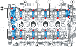
1. Loosen the camshaft cap installation bolts in a few passes in the order shown in the figure and remove the camshaft caps.
amxuuw00004381
|
2. Remove the camshaft.
Rocker Arm Removal Note
1. Keep the rocker arms in the order of removal to enable reassembly in their original positions.
Cylinder Head Removal Note
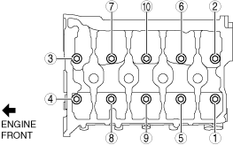
1. Loosen the cylinder head installation bolts in two or three passes in the order shown in the figure and remove them.
amxuuw00004382
|
2. Remove the cylinder head.
Cylinder Head Installation Note
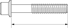
1. Measure the length of the cylinder head bolt
amxzzw00003984
|
2. When a cylinder head bolt is reused, apply engine oil to any part of the following:
3. Completely remove any oil, dirt, and sealant adhering to the cylinder block.
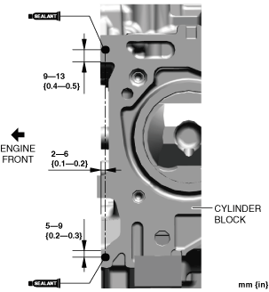
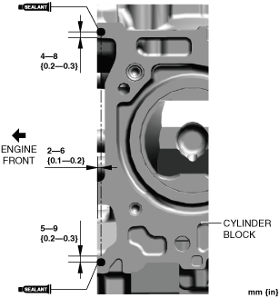
4. Apply silicone sealant (TB1217D or equivalent) to the areas shown in the figure.
SKYACTIV-G 1.5
amxzzw00004061
|
SKYACTIV-G 2.0
amxzzw00004062
|
5. Install a new cylinder head gasket to the cylinder block.
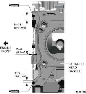
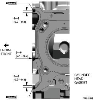
6. Apply silicone sealant (TB1217D or equivalent) to the areas shown in the figure.
SKYACTIV-G 1.5
amxzzw00004063
|
SKYACTIV-G 2.0
amxzzw00004064
|
7. Set the cylinder head on the cylinder block.
8. Tighten the cylinder head bolts in the order shown in the following 4 steps.
amxuuw00004383
|
Rocker Arm Installation Note
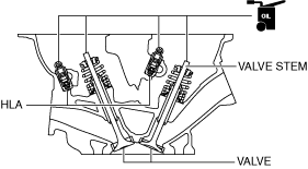
1. Apply engine oil to the HLAs and the end of the valve stems.
am3uuw00008819
|
2. Install the rocker arms to the same positions as before removal.
Camshaft Installation Note
1. Apply SAE 90 gear oil or equivalent, or engine oil to the positions shown in the figure.
amxuuw00004384
|
2. Apply SAE 90 gear oil or equivalent, or engine oil to the following locations of each camshaft.
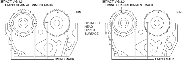
3. Install the camshaft with the timing chain alignment marks aligned as shown in the figure.
amxzzw00003015
|
4. Apply SAE 90 gear oil or equivalent, or engine oil to the central area of each journal on the camshaft.
amxuuw00004386
|
5. Apply SAE 90 gear oil or equivalent, or engine oil to the thrust surface of the front camshaft cap.
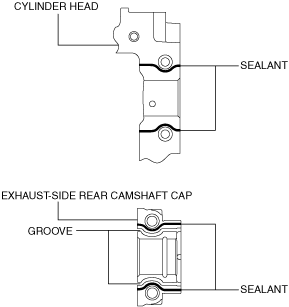
6. Apply sealant (LOCTITE 962T, 518, 272 or equivalent) to the rear camshaft cap installation area on the exhaust side or the rear camshaft caps on the exhaust side of the cylinder head.
am2zzw00011109
|
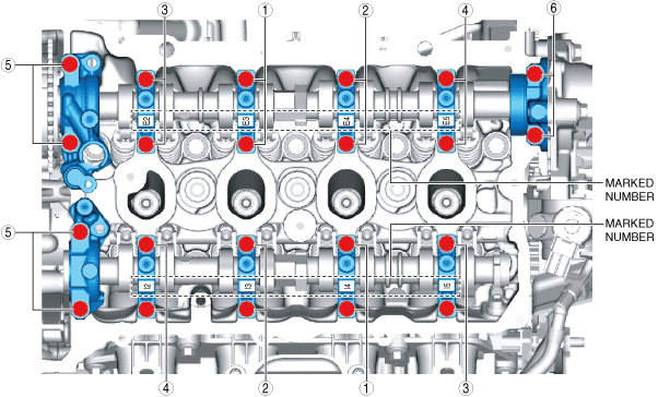
7. Install the camshaft caps in the order of the marked numbers, and temporarily tighten the camshaft cap installation bolts evenly in 2—3 rounds.
8. Tighten the camshaft cap installation bolts in two steps in the order shown in the figure.
amxuuw00004387
|