 |
amxuuw00004308
ENGINE MOUNT DISASSEMBLY/ASSEMBLY [SKYACTIV-G 1.5, SKYACTIV-G 2.0]
id0110h8806900
Engine Mount (RH)
1. Disconnect the negative battery terminal. (See NEGATIVE BATTERY TERMINAL DISCONNECTION/CONNECTION.)
2. Remove the bolt shown in the figure and set the ground cable aside.
amxuuw00004308
|
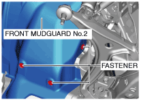
3. Remove the front wheels and tires (RH). (See GENERAL PROCEDURES (SUSPENSION).)
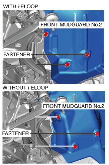
4. Remove the fasteners shown in the figure and slightly bend back the front mudguard No.2 (RH).
amxuuw00004309
|
5. Remove the front splash shield No.1 (RH). (See FRONT SPLASH SHIELD No.1 REMOVAL/INSTALLATION.)
6. Remove the front crossmember under cover. (See FRONT CROSSMEMBER UNDER COVER REMOVAL/INSTALLATION.)
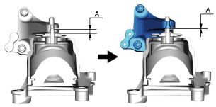
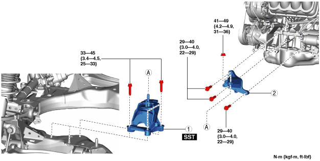
7. Remove in the order indicated in the table.
8. Install in the reverse order of removal.
amxzzw00004259
|
|
1
|
Engine mount rubber (RH)
|
|
2
|
Engine mount bracket (RH)
|
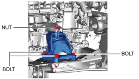
Engine mount rubber (RH) removal note
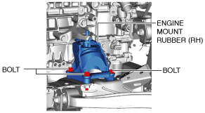
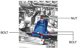
1. Remove the bolts and the nut shown in the figure.
amxuuw00004311
|
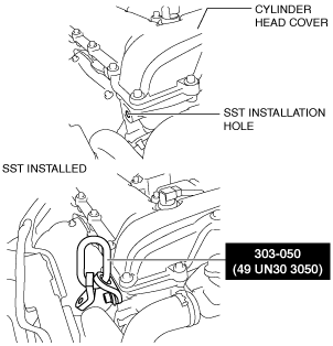
2. Install the SST to the position shown in the figure using the following bolt.
amxuuw00004312
|
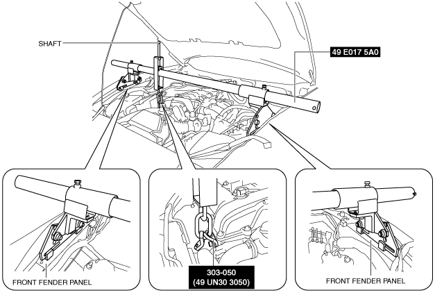
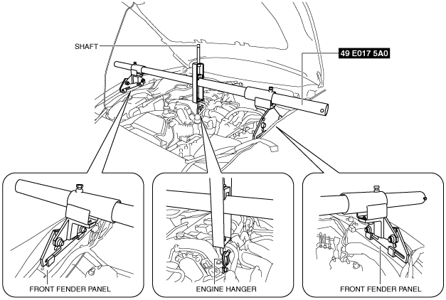
3. Set the SSTs (49 E017 5A0, 49 UN30 3050) as shown in the figure.
amxuuw00004313
|
4. Rotate the shaft of the SST (49 E017 5A0) to support the engine.
5. Rotate the shaft of the SST (49 E017 5A0) to lift up the engine and remove the engine mount rubber (RH).
amxuuw00004314
|
Engine mount rubber (RH) installation note
1. Install the engine mount rubber (RH) and lower the engine by rotating the shaft of the SST (49 E017 5A0) until the front crossmember is lightly seated.
2. Temporarily tighten the engine mount rubber (RH) installation bolts.
amxuuw00004315
|
3. Rotate the shaft of the SST (49 E017 5A0) and lower the engine more.
4. Tighten the engine mount rubber (RH) installation bolts.
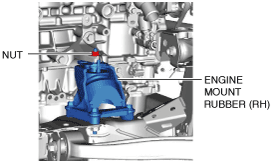
5. Tighten the engine mount rubber (RH) installation nut.
amxuuw00004316
|
Engine Mount (LH)
1. Disconnect the negative battery terminal. (See NEGATIVE BATTERY TERMINAL DISCONNECTION/CONNECTION.)
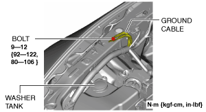
2. Remove the bolt shown in the figure and set the ground cable aside.
amxuuw00004308
|
3. Remove the front wheels and tires (LH). (See GENERAL PROCEDURES (SUSPENSION).)
4. Remove the fasteners shown in the figure and slightly bend back the front mudguard No.2 (LH).
amxzzw00003035
|
5. Remove the front splash shield No.1 (LH). (See FRONT SPLASH SHIELD No.1 REMOVAL/INSTALLATION.)
6. Remove in the order indicated in the table.
7. Install in the reverse order of removal.
amxzzw00004260
|
|
1
|
Engine mount rubber (LH)
|
|
2
|
Engine mount bracket (LH)
|
Engine mount rubber (LH) removal note
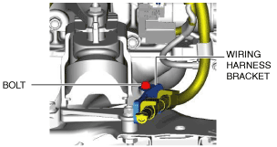
1. Remove the bolt shown in the figure and set the wiring harness bracket aside. (With i-ELOOP)
amxzzw00003637
|
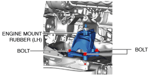
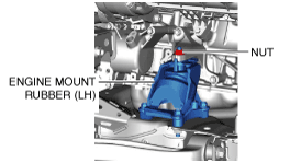
2. Remove the bolts and the nut shown in the figure.
amxuuw00004319
|
3. Set the SST (49 E017 5A0) as shown in the figure.
amxuuw00004320
|
4. Rotate the shaft of the SST (49 E017 5A0) to support the engine.
5. Rotate the shaft of the SST (49 E017 5A0) to lift up the engine and remove the engine mount rubber (LH).
amxuuw00004314
|
Engine mount bracket (LH) removal note
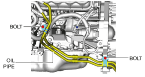
1. Remove the front crossmember under cover. (See FRONT CROSSMEMBER UNDER COVER REMOVAL/INSTALLATION.)
2. Remove the bolts shown in the figure and set the oil pipe aside. (AT)
amxuuw00004321
|
3. Remove the bolts shown in the figure and set the bracket aside. (AT)
amxuuw00004322
|
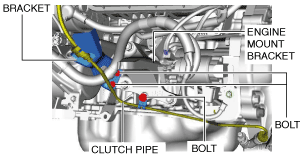
4. Remove the bolts shown in the figure and set the bracket and clutch pipe aside. (MT)
amxuuw00004323
|
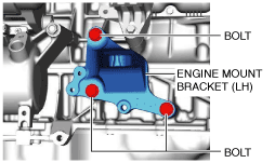
5. Remove the bolts shown in the figure and remove the engine mount bracket (LH).
amxuuw00004324
|
Engine mount bracket (LH) installation Note
1. Install the engine mount bracket (LH).
amxuuw00004324
|
2. Return the clutch pipe and bracket to their original positions and tighten the bolts. (MT)
amxuuw00004323
|
3. Return the bracket to their original positions and temporarily tighten the bolts. (AT)
amxuuw00004322
|
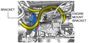
4. Tighten the bracket installation bolts in the order as shown in the figure.
amxuuw00004325
|
5. Return the oil pipe to their original positions and tighten the bolts. (AT) (See OIL COOLER REMOVAL/INSTALLATION [SJ6A-EL].)
Engine mount rubber (LH) installation note
1. Install the engine mount rubber (LH) and lower the engine by rotating the shaft of the SST (49 E017 5A0) until the front crossmember is lightly seated.
2. Temporarily tighten the engine mount rubber (LH) installation bolts.
amxuuw00004326
|
3. Rotate the shaft of the SST (49 E017 5A0) and lower the engine more.
4. Tighten the engine mount rubber (LH) installation bolts.
5. Tighten the engine mount rubber (LH) installation nut.
amxuuw00004327
|
6. Tighten the wiring harness bracket installation bolt. (With i-ELOOP)
amxzzw00003637
|
7. Install the front crossmember under cover. (See FRONT CROSSMEMBER UNDER COVER REMOVAL/INSTALLATION.)