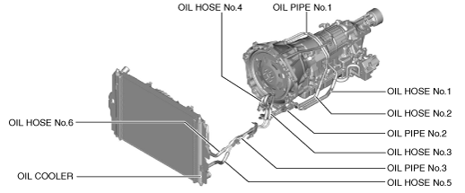
Note
• The figure shows the parts which are replaced in the following servicing procedure.
amxuuw00003481
|
OIL COOLER REMOVAL/INSTALLATION [SJ6A-EL]
id051311248700
amxuuw00003481
|
Oil Cooler Removal/Installation
1. If the oil cooler is replaced, also replace the radiator. (See RADIATOR REMOVAL/INSTALLATION [SKYACTIV-G 1.5, SKYACTIV-G 2.0].)
Oil Pipe No.1 Removal/Installation
1. Disconnect the negative battery terminal. (See NEGATIVE BATTERY TERMINAL DISCONNECTION/CONNECTION.)
2. Remove the selector lever knob. (See AUTOMATIC TRANSMISSION SHIFT MECHANISM REMOVAL/INSTALLATION.)
3. Remove the shift panel component. (See SHIFT PANEL REMOVAL/INSTALLATION.)
4. Remove the upper panel. (See UPPER PANEL REMOVAL/INSTALLATION.)
5. Remove the parking brake lever boot panel. (See PARKING BRAKE LEVER BOOT PANEL REMOVAL/INSTALLATION.)
6. Remove the rear console. (See REAR CONSOLE REMOVAL/INSTALLATION.)
7. Remove the front console panel. (See FRONT CONSOLE PANEL REMOVAL/INSTALLATION.)
8. Remove the front console component. (See FRONT CONSOLE REMOVAL/INSTALLATION.)
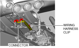
9. Disconnect the connector and wiring harness clip.
amxuuw00002845
|
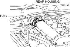
10. Place a clean rag behind the engine so that the engine does not contact the rear housing when it is tilted.
amxzzw00005232
|
11. Remove the front crossmember under cover. (See FRONT CROSSMEMBER UNDER COVER REMOVAL/INSTALLATION.)
12. Disconnect the control rod from the selector lever component. (See AUTOMATIC TRANSMISSION SHIFT MECHANISM REMOVAL/INSTALLATION.)
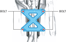
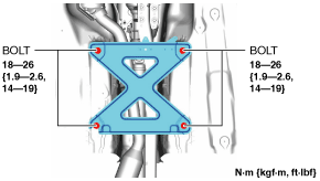
13. Remove the tunnel member.
amxuuw00003817
|
14. Disconnect the HO2S connector. (See HEATED OXYGEN SENSOR (HO2S) REMOVAL/INSTALLATION [SKYACTIV-G 1.5, SKYACTIV-G 2.0].)
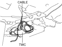
15. Disconnect the TWC from the exhaust manifold (WU-TWC). (See EXHAUST SYSTEM REMOVAL/INSTALLATION [SKYACTIV-G 1.5, SKYACTIV-G 2.0].)
16. Suspend the TWC using a cable as shown in the figure.
amxuuw00002847
|
17. Remove the power plant frame. (See POWER PLANT FRAME REMOVAL [M66M-D].)
18. Tilt the transmission while being careful not to allow parts on the back of the engine to contact the vehicle body.
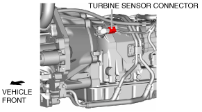
19. Disconnect the turbine sensor connector.
amxuuw00003526
|
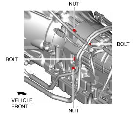
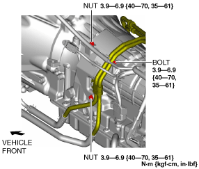
20. Remove the bolts and nuts.
amxzzw00003315
|
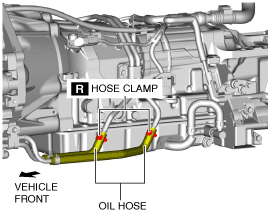
21. Disconnect the oil hose.
amxzzw00003320
|
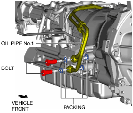
22. Remove the oil pipe No.1.
amxuuw00003484
|
23. Temporarily place oil pipe No.1 in its installation position.
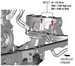
24. Install the bolt and nuts.
amxzzw00003316
|
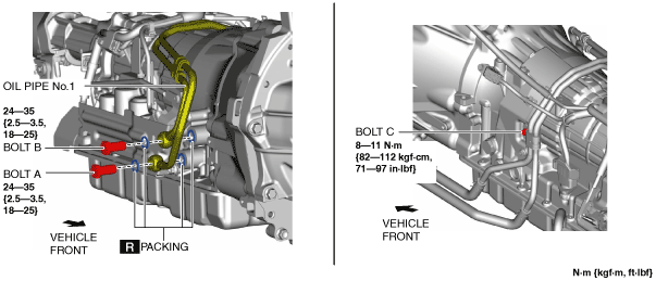
25. Install the oil pipe No.1 using the following procedure:
amxzzw00003317
|
26. Connect the oil hose. (See Oil Hose Installation Note.)
amxzzw00003320
|
27. Connect the turbine sensor connector.
amxuuw00003526
|
28. Install the power plant frame. (See POWER PLANT FRAME INSTALLATION [M66M-D].)
29. Remove the tunnel member temporarily.
amxuuw00003817
|
30. Connect the TWC to the exhaust manifold (WU-TWC). (See EXHAUST SYSTEM REMOVAL/INSTALLATION [SKYACTIV-G 1.5, SKYACTIV-G 2.0].)
31. Connect the HO2S connector. (See HEATED OXYGEN SENSOR (HO2S) REMOVAL/INSTALLATION [SKYACTIV-G 1.5, SKYACTIV-G 2.0].)
32. Install the tunnel member.
amxuuw00003818
|
33. Connect the control rod from the selector lever component. (See AUTOMATIC TRANSMISSION SHIFT MECHANISM REMOVAL/INSTALLATION.)
34. Install the front crossmember under cover. (See FRONT CROSSMEMBER UNDER COVER REMOVAL/INSTALLATION.)
35. Connect the connector and wiring harness clip.
amxuuw00002845
|
36. Install the front console component. (See FRONT CONSOLE REMOVAL/INSTALLATION.)
37. Install the front console panel. (See FRONT CONSOLE PANEL REMOVAL/INSTALLATION.)
38. Install the rear console. (See REAR CONSOLE REMOVAL/INSTALLATION.)
39. Install the parking brake lever boot panel. (See PARKING BRAKE LEVER BOOT PANEL REMOVAL/INSTALLATION.)
40. Install the upper panel. (See UPPER PANEL REMOVAL/INSTALLATION.)
41. Install the shift panel component. (See SHIFT PANEL REMOVAL/INSTALLATION.)
42. Install the selector lever knob. (See AUTOMATIC TRANSMISSION SHIFT MECHANISM REMOVAL/INSTALLATION.)
43. Connect the negative battery terminal. (See NEGATIVE BATTERY TERMINAL DISCONNECTION/CONNECTION.)
44. Inspect for oil leakage from the oil pipes and oil hoses.
45. Inspect the ATF level and condition. (See AUTOMATIC TRANSMISSION FLUID (ATF) INSPECTION [SJ6A-EL].)
Oil Hose No.1 and No.2 Removal/Installation
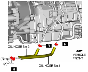
1. Remove the oil hose No.1 and No.2.
amxzzw00003318
|
2. Install the oil hose No.1 and No.2. (See Oil Hose Installation Note.)
3. Inspect for oil leakage from the oil pipes and oil hoses.
4. Inspect the ATF level and condition. (See AUTOMATIC TRANSMISSION FLUID (ATF) INSPECTION [SJ6A-EL].) (See AUTOMATIC TRANSMISSION FLUID (ATF) LEVEL ADJUSTMENT [SJ6A-EL].)
Oil Pipe No.2 Removal/Installation
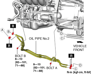
1. Remove the oil pipe No.2.
amxzzw00005233
|
2. Install the oil pipe No.2 using the following procedure:
3. Inspect for oil leakage from the oil pipes and oil hoses.
4. Inspect the ATF level and condition. (See AUTOMATIC TRANSMISSION FLUID (ATF) INSPECTION [SJ6A-EL].) (See AUTOMATIC TRANSMISSION FLUID (ATF) LEVEL ADJUSTMENT [SJ6A-EL].)
Oil Hose No.3 and No.4 Removal/Installation
1. Remove the front crossmember under cover. (See FRONT CROSSMEMBER UNDER COVER REMOVAL/INSTALLATION.)
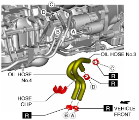
2. Remove the oil hose No.3 and No.4.
amxzzw00005234
|
3. Install in the reverse order of removal. (See Oil Hose Installation Note.)
4. Inspect for oil leakage from the oil pipes and oil hoses.
5. Inspect the ATF level and condition. (See AUTOMATIC TRANSMISSION FLUID (ATF) INSPECTION [SJ6A-EL].) (See AUTOMATIC TRANSMISSION FLUID (ATF) LEVEL ADJUSTMENT [SJ6A-EL].)
Oil Pipe No.3 Removal/Installation
1. Remove the front under cover. (See FRONT UNDER COVER REMOVAL/INSTALLATION.)
2. Remove the front crossmember under cover. (See FRONT CROSSMEMBER UNDER COVER REMOVAL/INSTALLATION.)
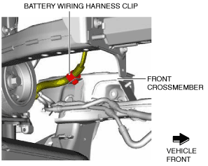
3. Disconnect the battery wiring harness clip.
amxzzw00005235
|
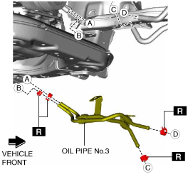
4. Remove the bolts.
amxzzw00005236
|
5. Remove the oil pipe No.3.
amxzzw00005237
|
6. Install in the reverse order of removal. (See Oil Hose Installation Note.)
7. Inspect for oil leakage from the oil pipes and oil hoses.
8. Inspect the ATF level and condition. (See AUTOMATIC TRANSMISSION FLUID (ATF) INSPECTION [SJ6A-EL].) (See AUTOMATIC TRANSMISSION FLUID (ATF) LEVEL ADJUSTMENT [SJ6A-EL].)
Oil Hose No.5 and No.6 Removal/Installation
1. Remove the front under cover. (See FRONT UNDER COVER REMOVAL/INSTALLATION.)
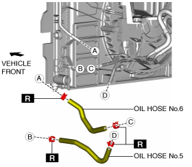
2. Remove the oil hose No.5 and No.6.
amxuuw00003493
|
3. Install in the reverse order of removal. (See Oil Hose Installation Note.) (See Oil Hose No.5 (Radiator Side) Installation Note.)
4. Inspect for oil leakage from the oil pipes and oil hoses.
5. Inspect the ATF level and condition. (See AUTOMATIC TRANSMISSION FLUID (ATF) INSPECTION [SJ6A-EL].) (See AUTOMATIC TRANSMISSION FLUID (ATF) LEVEL ADJUSTMENT [SJ6A-EL].)
Oil Hose Installation Note
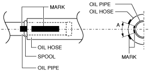
1. Align the marks on the hose and the pipe so that they are in a straight line.
amxuuw00003494
|
2. The marks on the hose and the pipe are within range A shown in the figure.
3. If the hose does not insert easily, use ATF as a lubricating agent.
4. Wipe off the ATF remaining on the hose and pipe after installing the hose.
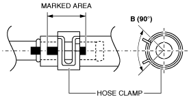
5. The hose clamp is within the marked area of the hose.
ac9wzw00003050
|
6. The hose clamp installation direction is within range B shown in the figure.
7. Install the hose clamp onto the hose. Then apply force to the hose clamp in the direction of the arrow in order to fit the clamp in place.
ardjjw00004938
|
8. Verify that the hose clamp does not interfere with any other components.
Oil Hose No.5 (Radiator Side) Installation Note
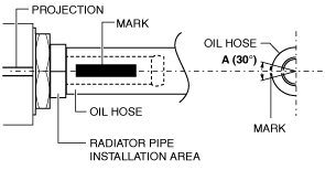
1. Align the oil hose marking with the projection on the radiator and insert the oil hose into the radiator pipe installation area until it is abutted.
amxuuw00003495
|
2. The marks on the hose are within range A shown in the figure.
3. If the hose does not insert easily, use ATF as a lubricating agent.
4. Wipe off the ATF remaining on the hose and pipe after installing the hose.
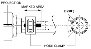
5. The hose clamp is within the marked area of the hose.
amxuuw00003496
|
6. The hose clamp installation direction is within range B shown in the figure.
7. Install the hose clamp onto the hose. Then apply force to the hose clamp in the direction of the arrow in order to fit the clamp in place.
ardjjw00004938
|
8. Verify that the hose clamp does not interfere with any other components.