Note
• There are two types of adjusting cam bolts.
amxzzw00004434
|
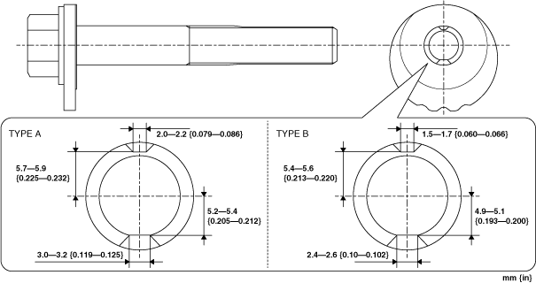
• Adjusting cam bolt type A cannot be reused.
• The nut used with adjusting cam bolt type A also cannot be reused.
FRONT LOWER ARM REMOVAL/INSTALLATION
id021300204011
amxzzw00004434
|
1. Remove the front ABS wheel-speed sensor from the wheel hub component.
amxuuw00005344
|
2. Remove the front ABS wheel-speed sensor wiring harness from the bracket and front upper arm and set it aside so that it does not interfere with the servicing.
3. Disconnect the front stabilizer control link from the front lower arm. (See FRONT STABILIZER REMOVAL/INSTALLATION.)
4. Disconnect the front shock absorber from the front lower arm. (See FRONT SHOCK ABSORBER AND COIL SPRING REMOVAL/INSTALLATION.)
5. Disconnect the tie-rod end from the steering knuckle. (See TIE-ROD END REPLACEMENT.)
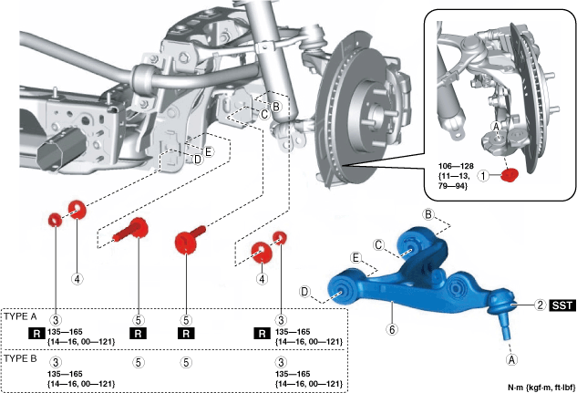
6. Remove in the order indicated in the table.
7. Install in the reverse order of removal.
8. Inspect the front wheel alignment and adjust it if necessary. (See FRONT WHEEL ALIGNMENT.)
amxzzw00004435
|
|
1
|
Front lower arm ball joint installation nut
|
|
2
|
Front lower arm ball joint
|
|
3
|
Nut
|
|
4
|
Cam plate
|
|
5
|
Adjusting cam bolt
|
|
6
|
Front lower arm
|
Front Lower Arm Ball Joint Installation Note
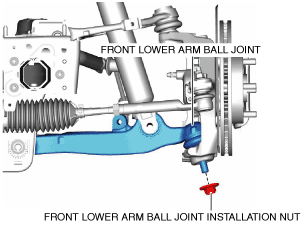
1. Loosen the front lower arm ball joint installation nut.
amxuuw00003393
|
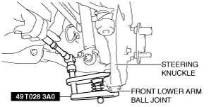
2. Disconnect the steering knuckle and front lower arm ball joint end using the SST.
amxuuw00003394
|
3. Remove the front lower arm ball joint installation nut.
amxuuw00003395
|
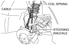
4. Suspend the steering knuckle to the coil spring as shown in the figure after removing the front lower arm ball joint.
amxuuw00003396
|
Adjusting Cam Bolt Installation Note
1. Install the front lower arm to the front crossmember and insert the adjusting cam bolts in the directions indicated as follows.
2. Point the calibration marking on the adjusting cam bolt and cam plate towards the underside of the vehicle.
3. Tighten the nut to the specified torque.