 |
amxzzw00004487
FRONT STABILIZER REMOVAL/INSTALLATION
id021300204013
1. Disconnect the negative battery terminal. (See NEGATIVE BATTERY TERMINAL DISCONNECTION/CONNECTION.)
2. Remove front mudguard No.1 and the front deflector as a single unit. (See FRONT MUDGUARD REMOVAL/INSTALLATION.)
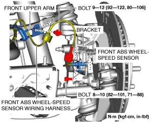
3. Remove the following parts:
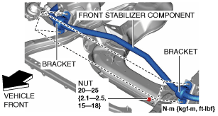
4. Remove the brackets.
amxzzw00004487
|
5. Remove the front ABS wheel-speed sensor from the wheel hub component.
amxuuw00005346
|
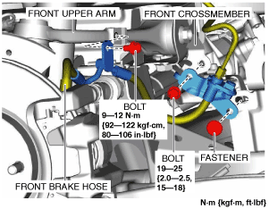
6. Remove the front ABS wheel-speed sensor wiring harness from the bracket and front upper arm and set it aside so that it does not interfere with the servicing.
7. Remove the front brake hose from the front upper arm and front crossmember and set it aside so that it does not interfere with the servicing.
amxuuw00005347
|
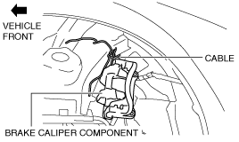
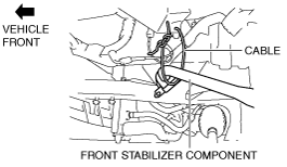
8. Remove the front brake caliper component and suspend it on the body side using a cable. (See FRONT BRAKE DISC REMOVAL/INSTALLATION [WITH 4-POT OPPOSED PISTON CALIPER].) (See FRONT BRAKE DISC REMOVAL/INSTALLATION [WITH SINGLE PISTON FLOATING CALIPER].)
amxuuw00003400
|
9. Remove the front disc plate. (See FRONT BRAKE DISC REMOVAL/INSTALLATION [WITH 4-POT OPPOSED PISTON CALIPER].) (See FRONT BRAKE DISC REMOVAL/INSTALLATION [WITH SINGLE PISTON FLOATING CALIPER].)
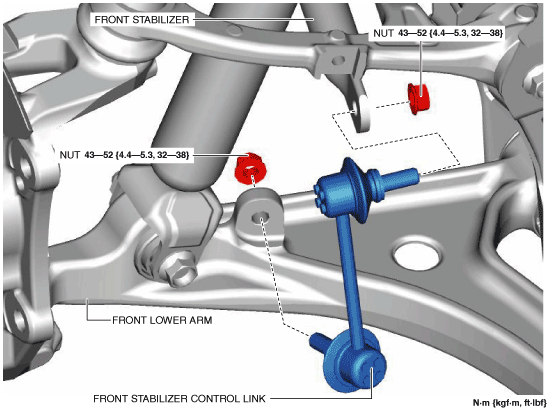
10. Remove the front stabilizer control link.
amxuuw00003401
|
11. Remove the front splash shield No.2. (See FRONT SPLASH SHIELD No.2 REMOVAL/INSTALLATION.)
12. Remove the nut. (See Nut Installation Note.)
amxuuw00003402
|
13. Suspend the front stabilizer component on the body side using a cable as shown in the figure.
amxuuw00003813
|
14. Disconnect the intermediate shaft from the steering gear and linkage. (See INTERMEDIATE SHAFT REMOVAL/INSTALLATION.)
15. Detach the wiring harness clip and connectors shown in the figure.
amxuuw00003404
|
16. Remove the front splash shield No.1. (See FRONT SPLASH SHIELD No.1 REMOVAL/INSTALLATION.)
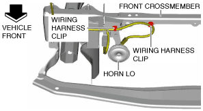
17. Detach the wiring harness clips shown in the figure.
amxzzw00003292
|
18. Remove the seal plate. (See SEAL PLATE REMOVAL/INSTALLATION.)
19. Remove the horn LO. (See HORN REMOVAL/INSTALLATION.)
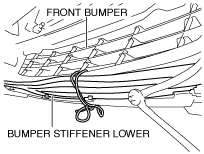
20. Remove the bumper stiffener lower. (With bumper stiffener lower) (See BUMPER STIFFENER LOWER REMOVAL/INSTALLATION.)
21. Secure the bumper stiffener lower to the front bumper using a cable. (With bumper stiffener lower)
amxuuw00003407
|
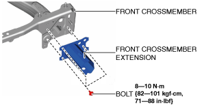
22. Remove the front crossmember extension.
amxuuw00005349
|
23. Remove the oil pipe No.3 bracket from the front crossmember. (AT vehicles) (See OIL COOLER REMOVAL/INSTALLATION [SJ6A-EL].)
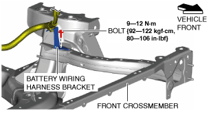
24. Remove the battery wiring harness bracket. (MT vehicles)
amxuuw00005350
|
25. Remove the coolant reserve tank. (See COOLANT RESERVE TANK REMOVAL/INSTALLATION [SKYACTIV-G 1.5, SKYACTIV-G 2.0].)
26. Remove the upper mount rubber bracket (LH). (See RADIATOR REMOVAL/INSTALLATION [SKYACTIV-G 1.5, SKYACTIV-G 2.0].)
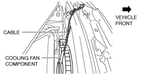
27. Suspend the cooling fan component through the upper mount rubber bracket (LH) hole using a cable as shown in the figure.
amxuuw00005351
|
28. Remove the lower radiator hose brackets from the front crossmember.
amxuuw00005352
|
29. Remove the lower mount rubber bracket. (See RADIATOR REMOVAL/INSTALLATION [SKYACTIV-G 1.5, SKYACTIV-G 2.0].)
30. Remove the center mount rubber bracket. (See RADIATOR REMOVAL/INSTALLATION [SKYACTIV-G 1.5, SKYACTIV-G 2.0].)
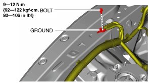
31. Remove the ground.
amxuuw00003684
|
32. Suspend the engine using the SST. (See ENGINE REMOVAL/INSTALLATION [SKYACTIV-G 1.5, SKYACTIV-G 2.0].)
33. Disconnect the engine mount rubber from the front crossmember. (See ENGINE MOUNT DISASSEMBLY/ASSEMBLY [SKYACTIV-G 1.5, SKYACTIV-G 2.0].)
34. Remove the front suspension tower bar. (With front suspension tower bar) (See FRONT SUSPENSION TOWER BAR REMOVAL/INSTALLATION.)
35. Remove the upper nuts of the front shock absorber. (See FRONT SHOCK ABSORBER AND COIL SPRING REMOVAL/INSTALLATION.)
36. Loosen the lower nut of the front shock absorber. (See FRONT SHOCK ABSORBER AND COIL SPRING REMOVAL/INSTALLATION.)
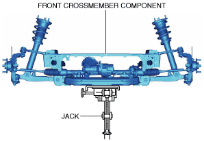
37. Support the front crossmember using a jack.
amxuuw00003413
|
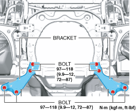
38. Remove in the order of bolts A, B, nuts A, and B.
amxuuw00003414
|
39. Lower the jack slowly and remove the front crossmember component.
40. Remove the front stabilizer component suspended above the vehicle. (See Front Stabilizer Component Installation Note.)
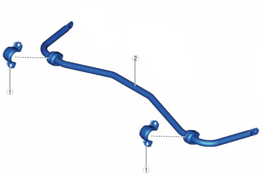
41. Remove in the order shown in the figure.
42. Install in the reverse order of removal.
43. Inspect the front wheel alignment and adjust it if necessary. (See FRONT WHEEL ALIGNMENT.)
ardjjw00003808
|
|
1
|
Front stabilizer bracket
|
|
2
|
Front stabilizer
|
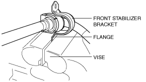
Front Stabilizer Bracket Removal Note
1. If the front stabilizer bracket cannot be removed by hand, remove it using a vise.
am2zzw00008275
|
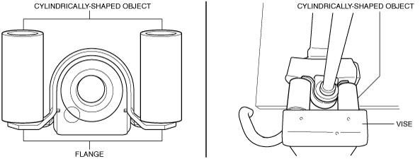
Front Stabilizer Bracket Installation Note
1. If the front stabilizer bracket cannot be installed by hand, install it using a vise.
amxuuw00005353
|
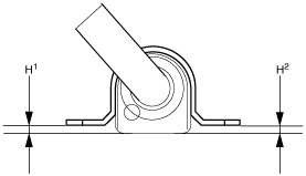
2. After installing the front stabilizer bracket, verify that the positions of the front stabilizer bracket and the front stabilizer bushing are within the range shown in the figure.
amxuuw00005354
|
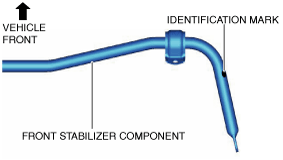
Front Stabilizer Component Installation Note
1. Assembly the front stabilizer component so that the identification mark is on the right side of the vehicle.
amxuuw00003415
|
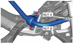
Nut Installation Note
1. Temporarily tighten nuts A and B shown in the figure.
amxuuw00003416
|
2. Tighten nut B.
3. Tighten nut A.
4. Tighten nut B.