|
1
|
VERIFY THAT OPERATION INDICATOR LIGHT TURNS ON WHEN REMOTE TRANSMITTER BUTTON IS USED
• Does the operation indicator light turn on?
|
Yes
|
Go to Step 4.
|
|
No
|
Go to the next step.
|
|
2
|
VERIFY IF PROBLEM IS DUE TO REMOTE TRANSMITTER POWER SAVING FUNCTION
• Turn off the power saving function.
• Does the operation indicator light turn on?
|
Yes
|
Perform the repair completion verification.
|
|
No
|
Go to the next step.
|
|
3
|
VERIFY BATTERY USED FOR REMOTE TRANSMITTER
• Is any of the following conditions met?
-
― Battery other than CR2025 is used (With remote transmitter type A)
― Battery other than CR2032 is used (With remote transmitter type B)
― Battery is inserted in opposite direction
― Battery voltage is low
|
Yes
|
Replace the remote transmitter battery and perform the repair completion verification.
|
|
No
|
Replace the remote transmitter and perform the repair completion verification.
|
|
4
|
DETERMINE IF MALFUNCTION CAUSE IS DOOR/ FUEL-FILLER LID LOCK
• Refer to “door lock does not operate” or “fuel-filler lid lock does not operate” symptom troubleshooting and perform the inspection.
• Is the advanced keyless entry system operating normally?
|
Yes
|
Troubleshooting completed.
(Explain the contents of the servicing to the customer.)
|
|
No
|
Go to the next step.
|
|
5
|
VERIFY IF MALFUNCTION CAUSE IS OPERATION OTHER THAN OPERATION PERMISSION CONDITION
• Verify the advanced keyless operation by operating each request switch and the trunk lid opener switch with all the following conditions met.
-
― All doors and trunk lid closed
― Ignition switched off
― Remote transmitter is within reception area (80 cm radius from driver's door, passenger's door, and trunk lid)
• Is the advanced keyless entry system operating normally?
|
Yes
|
System is normal.
(Explain to customer about operation range of advanced keyless entry system)
|
|
No
|
Go to the next step.
|
|
6
|
VERIFY IF MALFUNCTION CAUSE IS EXTRINSIC NOISE
• Ask the customer malfunction condition.
• Does the malfunction occur at the specified place where extrinsic noise is received such as a TV tower, electric power station, or a broadcast station?
|
Yes
|
System is normal.
(Explain the customer that operation cannot be performed caused by extrinsic noise.)
|
|
No
|
Go to the next step.
|
|
7
|
VERIFY MALFUNCTION SYMPTOM
• Does the trunk lid open using the trunk lid opener switch operation?
|
Yes
|
Go to Step 10.
(The trunk lid latch system is normal.)
|
|
No
|
Go to the next step.
|
|
8
|
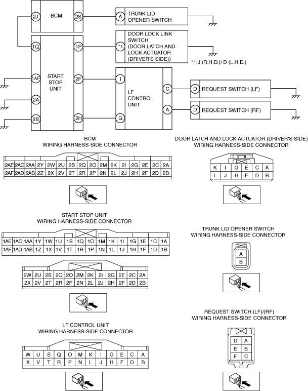
INSPECT TRUNK LID OPENER SWITCH-RELATED WIRING HARNESS (OPEN CIRCUIT)
• Disconnect the negative battery terminal.
• Disconnect the BCM and trunk lid opener switch connector.
• Inspect for continuity between the following terminals (vehicle wiring harness).
-
― Trunk lid opener switch terminal A and BCM terminal 2S
• Is there continuity?
|
Yes
|
Go to the next step.
|
|
No
|
• Refer to the wiring diagram and verify if there is a common connector between the following terminals.
-
― Trunk lid opener switch terminal A and BCM terminal 2S
If there is a common connector:
-
• Inspect the common connector and terminals for corrosion, damage, or disconnection and the common wiring harnesses for an open circuit to determine the malfunctioning location.
• Repair or replace the malfunctioning location.
If there is no common connector:
-
• Repair or replace the wiring harness which has an open circuit.
• Go to Step 15.
|
|
9
|
INSPECT TRUNK LID OPENER SWITCH
• Inspect the trunk lid opener switch.
• Is the trunk lid opener switch normal?
|
Yes
|
-
Note
-
• A trunk lid release actuator or trunk lid latch switch malfunction can be considered.
Replace the trunk lid latch and release actuator, then go to Step 15.
|
|
No
|
Replace the trunk lid opener switch, then go to Step 15.
|
|
10
|
VERIFY MALFUNCTION SYMPTOM
• Connect the negative battery terminal.
• Verify the lock/unlock operation for all doors, fuel-filler lid and trunk lid using the request switch operation.
• Is door or fuel-filler lid or trunk lid locked/unlocked?
|
Yes
|
Go to Step 15.
|
|
No
|
Go to the next step.
|
|
11
|
INSPECT DOOR LOCK LINK SWITCH-RELATED WIRING HARNESS (OPEN CIRCUIT)
• Disconnect the negative battery terminal.
• Disconnect the start stop unit and the door latch and lock actuator (driver's side) connector.
• Inspect for continuity between the following terminals (vehicle wiring harness).
-
― Start stop unit terminal 1P and door lock link switch terminal J (R.H.D.)/ D (L.H.D.)
• Is there continuity?
|
Yes
|
Go to the next step.
|
|
No
|
• Refer to the wiring diagram and verify if there is a common connector between the following terminals.
-
― Start stop unit terminal 1P and door lock link switch terminal J (R.H.D.)/ D (L.H.D.)
If there is a common connector:
-
• Inspect the common connector and terminals for corrosion, damage, or disconnection and the common wiring harnesses for an open circuit to determine the malfunctioning location.
• Repair or replace the malfunctioning location.
If there is no common connector:
-
• Repair or replace the wiring harness which has an open circuit.
• Go to Step 15.
|
|
12
|
INSPECT DOOR LOCK LINK SWITCH-RELATED WIRING HARNESS (SHORT TO GROUND)
• Verify that the start stop unit connector is disconnected.
• Inspect for continuity between the following wiring harness terminals (vehicle wiring harness side) and body ground.
-
― Start stop unit terminal 1P
• Is there continuity?
|
Yes
|
• Refer to the wiring diagram and verify if there is a common connector between the following terminals.
-
― Start stop unit terminal 1P and door lock link switch terminal J (R.H.D.)/ D (L.H.D.)
If there is a common connector:
-
• Inspect the common connector and terminals for corrosion, damage, or disconnection and the common wiring harnesses for an short to ground to determine the malfunctioning location.
• Repair or replace the malfunctioning location.
If there is no common connector:
-
• Repair or replace the wiring harness which has an short to ground.
• Go to Step 15.
|
|
No
|
Go to the next step.
|
|
13
|
INSPECT START STOP UNIT RELATED WIRING HARNESS (OPEN CIRCUIT)
• Verify that the start stop unit connector is disconnected.
• Inspect for continuity between the following terminals (vehicle wiring harness).
-
― Start stop unit terminal 1AF and ground
― Start stop unit terminal 2A and ground
― Start stop unit terminal 2B and ground
• Is there continuity?
|
Yes
|
Go to the next step.
|
|
No
|
• Refer to the wiring diagram and verify if there is a common connector between the following terminals.
-
― Start stop unit terminal 1AF and ground
― Start stop unit terminal 2A and ground
― Start stop unit terminal 2B and ground
If there is a common connector:
-
• Inspect the common connector and terminals for corrosion, damage, or disconnection and the common wiring harnesses for an open circuit to determine the malfunctioning location.
• Repair or replace the malfunctioning location.
If there is no common connector:
-
• Repair or replace the wiring harness which has an open circuit.
• Go to Step 15.
|
|
14
|
INSPECT REQUEST SWITCH RELATED WIRING HARNESS (OPEN CIRCUIT)
• Disconnect the LF control unit and request switch connector.
• Inspect for continuity between the following terminals (vehicle wiring harness).
-
― Request switch (RF) terminal D and LF control unit terminal A
― Request switch (LF) terminal D and LF control unit terminal C
• Is there continuity?
|
Yes
|
Go to the next step.
|
|
No
|
• Refer to the wiring diagram and verify if there is a common connector between the following terminals.
-
― Request switch (RF) terminal D and LF control unit terminal A
― Request switch (LF) terminal D and LF control unit terminal C
If there is a common connector:
-
• Inspect the common connector and terminals for corrosion, damage, or disconnection and the common wiring harnesses for an open circuit to determine the malfunctioning location.
• Repair or replace the malfunctioning location.
If there is no common connector:
-
• Repair or replace the wiring harness which has an open circuit.
• Go to the next step.
|
|
15
|
VERIFY IF MALFUNCTION CAUSE WAS CORRECTED
• Does the advanced keyless entry system operate normally?
|
Yes
|
Troubleshooting completed.
(Explain the contents of the servicing to the customer.)
|
|
No
|
If the malfunction has not been resolved, repeat the inspection from Step 1.
|