 |
amxzzw00005663
DETERMINING SHORT BETWEEN CIRCUITS LOCATION (HS-CAN) [R.H.D.]
id100226000800
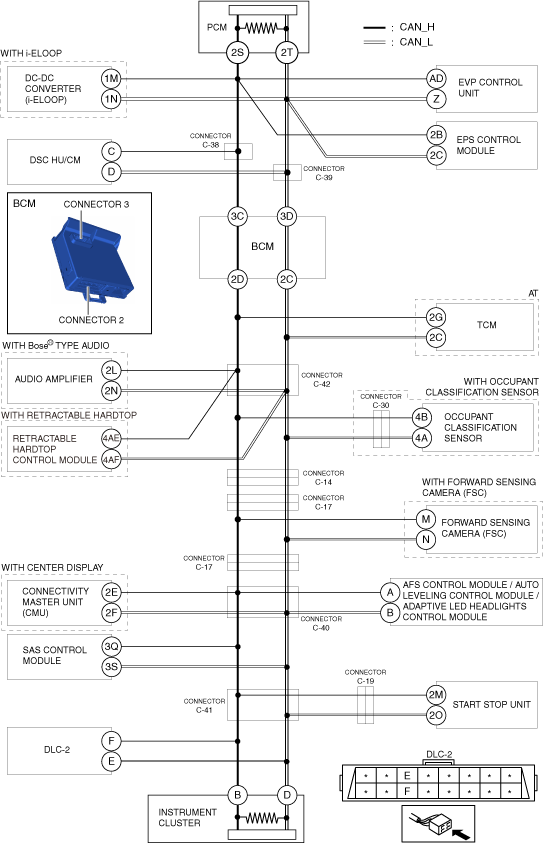
System Wiring Diagram
amxzzw00005663
|
Determination Procedure
|
Step |
Inspection |
Action |
|
|---|---|---|---|
|
1
|
INSPECT BETWEEN BCM AND INSTRUMENT CLUSTER FOR SHORT BETWEEN CIRCUITS
• Switch the ignition off.
• Disconnect the negative battery terminal.
• Disconnect the connector 2 and 3 which has BCM terminals 3C,3D and 2D,2C.
• Connect the negative battery terminal.
• Switch the ignition ON (engine off).
• Measure the voltage at DLC-2 terminals F and E.
• Is the voltage at DLC-2 terminals F and E the same?
|
Yes
|
Go to Step 10.
|
|
No
|
Go to the next step.
|
||
|
2
|
INSPECT BCM FOR SHORT BETWEEN CIRCUITS
• Switch the ignition off.
• Disconnect the negative battery terminal.
• Inspect for continuity between BCM terminals 3C and 3D.
• Is there continuity?
|
Yes
|
Replace the BCM because there is a short between circuits in the BCM.
|
|
No
|
Go to the next step.
|
||
|
3
|
INSPECT BETWEEN CONNECTORS C-38 AND C-39 AND BCM FOR SHORT BETWEEN CIRCUITS
• Disconnect the connectors C-38 and C-39.
• Inspect for continuity between BCM terminals 3C and 3D (wiring harness side).
• Is there continuity?
|
Yes
|
Repair or replace the wiring harness between the connectors C-38 and C-39 and BCM because the wiring harness is shorted between circuits.
|
|
No
|
Go to the next step.
|
||
|
4
|
INSPECT BETWEEN CONNECTORS C-38 AND C-39 AND DSC HU/CM FOR SHORT BETWEEN CIRCUITS
• Inspect for continuity between DSC HU/CM terminals C and D.
• Is there continuity?
|
Yes
|
Go to the next step.
|
|
No
|
Go to Step 6.
|
||
|
5
|
INSPECT DSC HU/CM FOR SHORT BETWEEN CIRCUITS
• Disconnect the DSC HU/CM connector.
• Inspect for continuity between DSC HU/CM terminals C and D (wiring harness side).
• Is there continuity?
|
Yes
|
Repair or replace the wiring harness between the connectors C-38 and C-39 and DSC HU/CM because the wiring harness is shorted between circuits.
|
|
No
|
Replace the DSC HU/CM because there is a short between circuits in the DSC HU/CM.
|
||
|
6
|
INSPECT PCM FOR SHORT BETWEEN CIRCUITS
• Disconnect the PCM connector.
• Inspect for continuity between PCM terminals 2S and 2T (wiring harness side).
• Is there continuity?
|
Yes
|
Go to the next step.
|
|
No
|
Replace the PCM because there is a short between circuits in the PCM.
|
||
|
7
|
INSPECT DC-DC CONVERTER (i-ELOOP) FOR SHORT BETWEEN CIRCUITS
• Disconnect the DC-DC converter (i-ELOOP) connector.
• Inspect for continuity between DC-DC converter (i-ELOOP) terminals 1M and 1N (wiring harness side).
• Is there continuity?
|
Yes
|
Go to the next step.
|
|
No
|
Replace the DC-DC converter (i-ELOOP) because there is a short between circuits in the DC-DC converter (i-ELOOP).
|
||
|
8
|
INSPECT EVP CONTROL UNIT FOR SHORT BETWEEN CIRCUITS
• Disconnect the EVP control unit connector.
• Inspect for continuity between EVP control unit terminals AD and Z (wiring harness side).
• Is there continuity?
|
Yes
|
Go to the next step.
|
|
No
|
Replace the EVP control unit because there is a short between circuits in the EVP control unit.
|
||
|
9
|
INSPECT EPS CONTROL MODULE FOR SHORT BETWEEN CIRCUITS
• Disconnect the EPS control module connector.
• Inspect for continuity between EPS control module terminals 2B and 2C (wiring harness side).
• Is there continuity?
|
Yes
|
Repair or replace the wiring harness between the PCM and connectors C-38 and C-39 because the wiring harness is shorted between circuits.
|
|
No
|
Replace the EPS control module because there is a short between circuits in the EPS control module.
|
||
|
10
|
INSPECT BETWEEN CONNECTOR C-42 AND INSTRUMENT CLUSTER FOR SHORT BETWEEN CIRCUITS
• Switch the ignition off.
• Disconnect the negative battery terminal.
• Disconnect the connector C-42.
• Connect the negative battery terminal.
• Switch the ignition ON (engine off).
• Measure the voltage at DLC-2 terminals F and E.
• Is the voltage at DLC-2 terminals F and E the same?
|
Yes
|
Go to Step 16.
|
|
No
|
Go to the next step.
|
||
|
11
|
INSPECT BETWEEN AUDIO AMPLIFIER AND CONNECTOR C-42 FOR SHORT BETWEEN CIRCUITS
• Switch the ignition off.
• Disconnect the negative battery terminal.
• Inspect for continuity between audio amplifier terminal terminals 2L and 2N.
• Is there continuity?
|
Yes
|
Go to the next step.
|
|
No
|
Go to Step 13.
|
||
|
12
|
INSPECT AUDIO AMPLIFIER FOR SHORT BETWEEN CIRCUITS
• Disconnect the audio amplifier connector.
• Inspect for continuity between audio amplifier terminals 2L and 2N (wiring harness side).
• Is there continuity?
|
Yes
|
Repair or replace the wiring harness between the audio amplifier and connector C-42 because the wiring harness is shorted between circuits.
|
|
No
|
Replace the audio amplifier because there is a short between circuits in the audio amplifier.
|
||
|
13
|
INSPECT BETWEEN RETRACTABLE HARDTOP CONTROL MODULE AND CONNECTOR C-42 FOR SHORT BETWEEN CIRCUITS
• Inspect for continuity between retractable hardtop control module terminal terminals 4AE and 4AF.
• Is there continuity?
|
Yes
|
Go to the next step.
|
|
No
|
Go to Step 15.
|
||
|
14
|
INSPECT RETRACTABLE HARDTOP CONTROL MODULE FOR SHORT BETWEEN CIRCUITS
• Disconnect the retractable hardtop control module connector.
• Inspect for continuity between retractable hardtop control module terminals 4AE and 4AF (wiring harness side).
• Is there continuity?
|
Yes
|
Repair or replace the wiring harness between the retractable hardtop control module and connector C-42 because the wiring harness is shorted between circuits.
|
|
No
|
Replace the retractable hardtop control module because there is a short between circuits in the retractable hardtop control module.
|
||
|
15
|
INSPECT TCM FOR SHORT BETWEEN CIRCUITS
• Disconnect the TCM connector.
• Inspect for continuity between TCM terminals 2G and 2C (wiring harness side).
• Is there continuity?
|
Yes
|
Repair or replace the wiring harness between the TCM and BCM and connector C-42 because the wiring harness is shorted between circuits.
|
|
No
|
Replace the TCM because there is a short between circuits in the TCM.
|
||
|
16
|
INSPECT BETWEEN CONNECTOR C-14 AND INSTRUMENT CLUSTER FOR SHORT BETWEEN CIRCUITS
• Switch the ignition off.
• Disconnect the negative battery terminal.
• Disconnect the connector C-14.
• Connect the negative battery terminal.
• Switch the ignition ON (engine off).
• Measure the voltage at DLC-2 terminals F and E.
• Is the voltage at DLC-2 terminals F and E the same?
|
Yes
|
Go to Step 19.
|
|
No
|
Go to the next step.
|
||
|
17
|
INSPECT BETWEEN CONNECTOR C-42 AND CONNECTOR C-30 AND CONNECTOR C-14 FOR SHORT BETWEEN CIRCUITS
• Switch the ignition off.
• Disconnect the negative battery terminal.
• Disconnect the connector C-30.
• Inspect for continuity between occupant classification sensor terminals 4B and 4A.
• Is there continuity?
|
Yes
|
Go to the next step.
|
|
No
|
Repair or replace the wiring harness between the connector C-42 and connector C-30 and connector C-14 because the wiring harness is shorted between circuits.
|
||
|
18
|
INSPECT OCCUPANT CLASSIFICATION SENSOR FOR SHORT BETWEEN CIRCUITS
• Disconnect the occupant classification sensor connector.
• Inspect for continuity between occupant classification sensor terminals 4B and 4A (wiring harness side).
• Is there continuity?
|
Yes
|
Repair or replace the wiring harness between the occupant classification sensor and connector C-30 because the wiring harness is shorted between circuits.
|
|
No
|
Replace the occupant classification sensor because there is a short between circuits in the occupant classification sensor.
|
||
|
19
|
INSPECT BETWEEN CONNECTOR C-17 AND INSTRUMENT CLUSTER FOR SHORT BETWEEN CIRCUITS
• Switch the ignition off.
• Disconnect the negative battery terminal.
• Disconnect the connector C-17.
• Connect the negative battery terminal.
• Switch the ignition ON (engine off).
• Measure the voltage at DLC-2 terminals F and E.
• Is the voltage at DLC-2 terminals F and E the same?
|
Yes
|
Go to Step 22.
|
|
No
|
Go to the next step.
|
||
|
20
|
INSPECT BETWEEN FORWARD SENSING CAMERA (FSC) AND CONNECTOR C-17 FOR SHORT BETWEEN CIRCUITS
• Switch the ignition off.
• Disconnect the negative battery terminal.
• Inspect for continuity between forward sensing camera (FSC) terminal terminals M and N.
• Is there continuity?
|
Yes
|
Go to the next step.
|
|
No
|
Repair or replace the wiring harness between the connector C-14 and connector C-17 because the wiring harness is shorted between circuits.
|
||
|
21
|
INSPECT FORWARD SENSING CAMERA (FSC) FOR SHORT BETWEEN CIRCUITS
• Disconnect the forward sensing camera (FSC) connector.
• Inspect for continuity between forward sensing camera (FSC) terminals M and N (wiring harness side).
• Is there continuity?
|
Yes
|
Repair or replace the wiring harness between the forward sensing camera (FSC) and connector C-17 because the wiring harness is shorted between circuits.
|
|
No
|
Replace the forward sensing camera (FSC) because there is a short between circuits in the forward sensing camera (FSC).
|
||
|
22
|
INSPECT BETWEEN CONNECTOR C-40 AND INSTRUMENT CLUSTER FOR SHORT BETWEEN CIRCUITS
• Switch the ignition off.
• Disconnect the negative battery terminal.
• Disconnect the connector C-40.
• Connect the negative battery terminal.
• Switch the ignition ON (engine off).
• Measure the voltage at DLC-2 terminals F and E.
• Is the voltage at DLC-2 terminals F and E the same?
|
Yes
|
Go to Step 27.
|
|
No
|
Go to the next step.
|
||
|
23
|
INSPECT BETWEEN CONNECTIVITY MASTER UNIT (CMU) AND CONNECTO C-40 FOR SHORT BETWEEN CIRCUITS
• Switch the ignition off.
• Disconnect the negative battery terminal.
• Inspect for continuity between connectivity master unit (CMU) terminals 2E and 2F.
• Is there continuity?
|
Yes
|
Go to the next step.
|
|
No
|
Go to Step 25.
|
||
|
24
|
INSPECT CONNECTIVITY MASTER UNIT (CMU) FOR SHORT BETWEEN CIRCUITS
• Disconnect the connectivity master unit (CMU) connector.
• Inspect for continuity between connectivity master unit (CMU) terminals 2E and 2F (wiring harness side).
• Is there continuity?
|
Yes
|
Repair or replace the wiring harness between the connectivity master unit (CMU) and connector C-40 because the wiring harness is shorted between circuits.
|
|
No
|
Replace the connectivity master unit (CMU) because there is a short between circuits in the connectivity master unit (CMU).
|
||
|
25
|
INSPECT BETWEEN AFS CONTROL MODULE / AUTO LEVELING CONTROL MODULE / ADAPTIVE LED HEADLIGHTS CONTROL MODULE AND CONNECTOR C-40 FOR SHORT BETWEEN CIRCUITS
• Inspect for continuity between AFS control module / auto leveling control module / adaptive LED headlights control module terminals A and B.
• Is there continuity?
|
Yes
|
Go to the next step.
|
|
No
|
Repair or replace the wiring harness between the connector C-17 and connector C-40 because the wiring harness is shorted between circuits.
|
||
|
26
|
INSPECT AFS CONTROL MODULE / AUTO LEVELING CONTROL MODULE / ADAPTIVE LED HEADLIGHTS CONTROL MODULE FOR SHORT BETWEEN CIRCUITS
• Disconnect the AFS control module / auto leveling control module / adaptive LED headlights control module connector.
• Inspect for continuity between AFS control module / auto leveling control module / adaptive LED headlights control module terminals A and B (wiring harness side).
• Is there continuity?
|
Yes
|
Repair or replace the wiring harness between the AFS control module / auto leveling control module / adaptive LED headlights control module and connector C-40 because the wiring harness is shorted between circuits.
|
|
No
|
Replace the AFS control module / auto leveling control module / adaptive LED headlights control module because there is a short between circuits in the AFS control module / auto leveling control module / adaptive LED headlights control module.
|
||
|
27
|
INSPECT BETWEEN CONNECTOR C-41 AND INSTRUMENT CLUSTER FOR SHORT BETWEEN CIRCUITS
• Switch the ignition off.
• Disconnect the negative battery terminal.
• Disconnect the connector C-41.
• Connect the negative battery terminal.
• Switch the ignition ON (engine off).
• Measure the voltage at DLC-2 terminals F and E.
• Is the voltage at DLC-2 terminals F and E the same?
|
Yes
|
Go to Step 32.
|
|
No
|
Go to the next step.
|
||
|
28
|
INSPECT BETWEEN START STOP UNIT AND CONNECTOR C-41 FOR SHORT BETWEEN CIRCUITS
• Switch the ignition off.
• Disconnect the negative battery terminal.
• Inspect for continuity between start stop unit terminals 2M and 2O.
• Is there continuity?
|
Yes
|
Go to the next step.
|
|
No
|
Go to Step 31.
|
||
|
29
|
INSPECT BETWEEN START STOP UNIT AND CONNECTOR C-19 FOR SHORT BETWEEN CIRCUITS
• Disconnect the connector C-19.
• Inspect for continuity between start stop unit terminals 2M and 2O.
• Is there continuity?
|
Yes
|
Go to the next step.
|
|
No
|
Repair or replace the wiring harness between the connector C-19 and connector C-41 because the wiring harness is shorted between circuits.
|
||
|
30
|
INSPECT START STOP UNIT FOR SHORT BETWEEN CIRCUITS
• Disconnect the start stop unit connector.
• Inspect for continuity between start stop unit terminals 2M and 2O (wiring harness side).
• Is there continuity?
|
Yes
|
Repair or replace the wiring harness between the start stop unit and connector C-19 because the wiring harness is shorted between circuits.
|
|
No
|
Replace the start stop unit because there is a short between circuits in the start stop unit.
|
||
|
31
|
INSPECT SAS CONTORL MODULE FOR SHORT BETWEEN CIRCUITS
• Disconnect the SAS control module connector.
• Inspect for continuity between SAS control module terminals 3Q and 3S (wiring harness side).
• Is there continuity?
|
Yes
|
Repair or replace the wiring harness between the SAS control module and connector C-40 and connector C-41 because the wiring harness is shorted between circuits.
|
|
No
|
Replace the SAS control module because there is a short between circuits in the SAS control module.
|
||
|
32
|
INSPECT INSTRUMENT CLUSTER FOR SHORT BETWEEN CIRCUITS
• Switch the ignition off.
• Disconnect the negative battery terminal.
• Disconnect the instrument cluster connector.
• Inspect for continuity between DLC-2 terminals F and E.
• Is there continuity?
|
Yes
|
Repair or replace the wiring harness between connector C-41 and instrument cluster and DLC-2 because the wiring harness is shorted between circuits.
|
|
No
|
Replace the instrument cluster because there is a short between circuits in the instrument cluster.
|
||