 |
amxzzw00003609
DTC P0011:00, P0012:00 [PCM (SKYACTIV-G 1.5, SKYACTIV-G 2.0)]
id0102i6710100
Details On DTCs
|
DESCRIPTION |
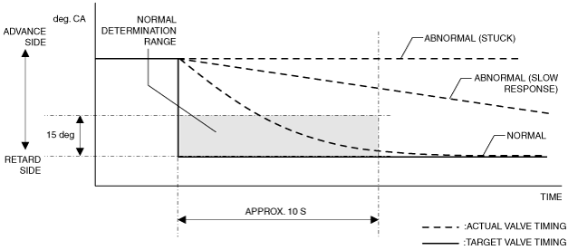
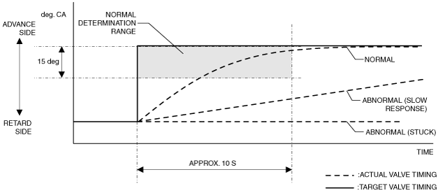
Electric variable valve timing control system: • P0011:00: Over-advanced
• P0012:00: Over-retarded
|
|
|---|---|---|
|
DETECTION CONDITION
|
Determination conditions
|
• P0011:00: For the advance amount from the maximum intake valve retard position, a condition in which the actual advance amount is larger than the target value continues for a specified period of time.
|
|
• P0012:00: For the advance amount from the maximum intake valve retard position, a condition in which the actual advance amount is smaller than the target value continues for a specified period of time.
|
||
|
Preconditions
|
• Battery voltage: above 11 V*1
• Engine speed: 5,000 rpm or less*1
• Engine coolant temperature: 20 °C {68 °F} or more*1
• The following DTCs are not detected:
*1: Value can be verified by displaying PIDs using M-MDS
|
|
|
Malfunction determination period
|
• 10 s period
|
|
|
Drive cycle
|
• 1
|
|
|
Self test type
|
• CMDTC self test
|
|
|
Sensor used
|
• CKP sensor
• Intake CMP sensor
|
|
|
FAIL-SAFE FUNCTION
|
• Not applicable
|
|
|
VEHICLE STATUS WHEN DTCs ARE OUTPUT
|
• Illuminates check engine light.
|
|
|
POSSIBLE CAUSE
|
• Electric variable valve timing motor/driver connectors or terminals malfunction
• Short to ground or open circuit in electric variable valve timing relay power supply circuit (without i-ELOOP)
• Short to ground or open circuit in electric variable valve timing relay power supply circuit (with i-ELOOP)
• Short to ground in wiring harness between the following terminals:
• Open circuit in wiring harness between the following terminals:
• PCM connector or terminals malfunction
• Electric variable valve timing relay malfunction
• Electric variable valve timing motor malfunction
• Electric variable valve timing actuator malfunction
• Timing chain malfunction
• Mis-detection of intake CMP sensor
• Mis-detection of CKP sensor
• PCM malfunction
|
|
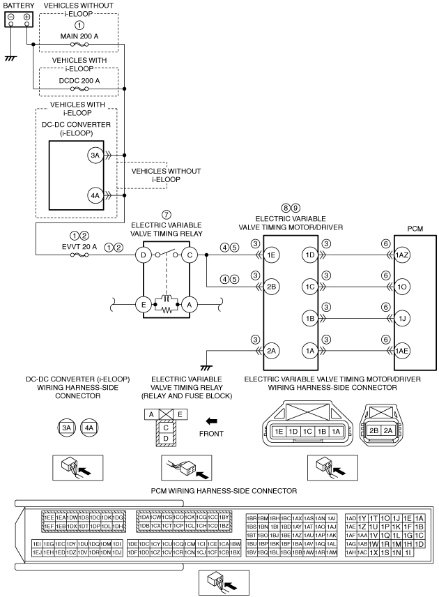
System Wiring Diagram
amxzzw00003609
|
Function Explanation (DTC Detection Outline)
am6zzw00011803
|
am3zzw00014488
|
Repeatability Verification Procedure
PID Item/Simulation Item Used In Diagnosis
PID/DATA monitor item table
|
Item |
Definition |
Unit |
Condition/Specification |
|---|---|---|---|
|
VT_IN_ACT
|
Actual intake variable valve timing control
• Advance amount from max retard position
|
°(deg)
|
• Displays actual intake variable valve timing—advance amount from max retard position
Ignition switched ON (engine off)
Idle (after warm up)
Racing (engine speed is 2,000 rpm)
Racing (engine speed is 4,000 rpm)
|
|
VT_IN_DES
|
Target intake variable valve timing control
• Advance amount from max retard position
|
°(deg)
|
• Displays target intake variable valve timing—advance amount from max retard position
Ignition switched ON (engine off)
Idle (after warm up)
Racing (engine speed is 2,000 rpm)
Racing (engine speed is 4,000 rpm)
|
Function Inspection Using M-MDS
|
STEP |
INSPECTION |
RESULTS |
ACTION |
|---|---|---|---|
|
1
|
PURPOSE: VERIFY RELATED SERVICE INFORMATION AVAILABILITY
• Verify related Service Information availability.
• Is any related Service Information available?
|
Yes
|
Perform repair or diagnosis according to the available Service Information.
• If the vehicle is not repaired, go to the next step.
|
|
No
|
Go to the next step.
|
||
|
2
|
PURPOSE: RECORD VEHICLE STATUS AT TIME OF DTC DETECTION TO UTILIZE WITH REPEATABILITY VERIFICATION
• Record the FREEZE FRAME DATA/snapshot data on the repair order.
|
—
|
Go to the next step.
|
|
3
|
PURPOSE: VERIFY IF DIAGNOSTIC RESULT IS AFFECTED BY OTHER RELATED DTCs OCCURRING
• Switch the ignition off, then ON (engine off).
• Perform the Pending Trouble Code Access Procedure and DTC Reading Procedure.
• Is the PENDING CODE/DTC P0010:00, P0335:00, P0340:00 or P1380:00 also present?
|
Yes
|
Go to the applicable DTC inspection.
Go to the next step.
|
|
No
|
Go to the next step.
|
||
|
4
|
PURPOSE: VERIFY CONFORMITY OF ACTUAL INTAKE VALVE TIMING
• Start the engine and idle it.
• Access the following PIDs using the M-MDS:
• Perform the following:
• Does the monitor value of the PID item VT_IN_ACT conform to the VT_IN_DES PID value?
|
Yes
|
Go to the next step.
|
|
No
|
Vehicles with i-ELOOP:
• Go to the troubleshooting procedure to perform the procedure from Step 2.
Vehicles without i-ELOOP:
• Go to the troubleshooting procedure to perform the procedure from Step 1.
|
||
|
5
|
PURPOSE: VERIFY CONNECTOR CONNECTIONS
• Start the engine.
• Access the VT_IN_ACT PID using the M-MDS.
• Does the PID value fluctuate when the following connectors are shaken?
|
Yes
|
Repair or replace the applicable wiring harness or connector parts.
Go to the troubleshooting procedure to perform the procedure from Step 13.
|
|
No
|
Vehicles with i-ELOOP:
• Go to the troubleshooting procedure to perform the procedure from Step 2.
Vehicles without i-ELOOP:
• Go to the troubleshooting procedure to perform the procedure from Step 1.
|
Troubleshooting Diagnostic Procedure
|
STEP |
INSPECTION |
RESULTS |
ACTION |
|---|---|---|---|
|
1
|
PURPOSE: INSPECT ELECTRIC VARIABLE VALVE TIMING RELAY POWER SUPPLY CIRCUIT FOR SHORT TO GROUND OR OPEN CIRCUIT
• Switch the ignition off.
• Remove the electric variable valve timing relay.
(See RELAY LOCATION.)
• Measure the voltage at the electric variable valve timing relay terminal D (wiring harness-side).
• Is the voltage B+?
|
Yes
|
Go to Step 3.
|
|
No
|
Inspect the MAIN 200 A fuse and EVVT 20 A fuse.
• If the fuse is blown:
• If the fuse is damaged:
• If all fuses are normal:
Go to Step 13.
|
||
|
2
|
PURPOSE: INSPECT ELECTRIC VARIABLE VALVE TIMING RELAY POWER SUPPLY CIRCUIT FOR SHORT TO GROUND OR OPEN CIRCUIT
• Switch the ignition off.
• Remove the electric variable valve timing relay.
(See RELAY LOCATION.)
• Measure the voltage at the electric variable valve timing relay terminal D (wiring harness-side).
• Is the voltage B+?
|
Yes
|
Go to the next step.
|
|
No
|
Remove the service plug.
Inspect the EVVT 20 A fuse.
• If the fuse is blown:
• If the fuse is damaged:
• If the fuse is normal:
Reinstall the service plug.
Go to Step 13.
|
||
|
3
|
PURPOSE: INSPECT ELECTRIC VARIABLE VALVE TIMING MOTOR/DRIVER CONNECTOR CONDITION
• Disconnect the electric variable valve timing motor/driver connector.
• Inspect for poor connection (such as damaged/pulled-out pins, corrosion).
• Is there any malfunction?
|
Yes
|
Repair or replace the connector and/or terminals, then go to Step 13.
|
|
No
|
Go to the next step.
|
||
|
4
|
PURPOSE: INSPECT ELECTRIC VARIABLE VALVE TIMING RELAY CONTROL CIRCUIT FOR SHORT TO GROUND
• Electric variable valve timing relay is removed.
• Verify that the electric variable valve timing motor/driver connector is disconnected.
• Inspect for continuity between electric variable valve timing relay terminal C (wiring harness-side) and body ground.
• Is there continuity?
|
Yes
|
Refer to the wiring diagram and verify whether or not there is a common connector between the following terminals:
• Electric variable valve timing relay terminal C—Electric variable valve timing motor/driver terminal 1E
• Electric variable valve timing relay terminal C—Electric variable valve timing motor/driver terminal 2B
If there is a common connector:
• Determine the malfunctioning part by inspecting the common connector and the terminal for corrosion, damage, or pin disconnection, and the common wiring harness for a short to ground.
• Repair or replace the malfunctioning part.
If there is no common connector:
• Repair or replace the wiring harness which has a short to ground.
Go to Step 13.
|
|
No
|
Go to the next step.
|
||
|
5
|
PURPOSE: INSPECT ELECTRIC VARIABLE VALVE TIMING RELAY CONTROL CIRCUIT FOR OPEN CIRCUIT
• Electric variable valve timing relay is removed.
• Verify that the electric variable valve timing motor/driver connector is disconnected.
• Inspect for continuity between the following terminals (wiring harness-side):
• Is there continuity?
|
Yes
|
Go to the next step.
|
|
No
|
Refer to the wiring diagram and verify whether or not there is a common connector between the following terminals:
• Electric variable valve timing relay terminal C—Electric variable valve timing motor/driver terminal 1E
• Electric variable valve timing relay terminal C—Electric variable valve timing motor/driver terminal 2B
If there is a common connector:
• Determine the malfunctioning part by inspecting the common connector and the terminal for corrosion, damage, or pin disconnection, and the common wiring harness for an open circuit.
• Repair or replace the malfunctioning part.
If there is no common connector:
• Repair or replace the wiring harness which has an open circuit.
Go to Step 13.
|
||
|
6
|
PURPOSE: INSPECT PCM CONNECTOR CONDITION
• Disconnect the PCM connector.
• Inspect for poor connection (such as damaged/pulled-out pins, corrosion).
• Is there any malfunction?
|
Yes
|
Repair or replace the connector and/or terminals, then go to Step 13.
|
|
No
|
Go to the next step.
|
||
|
7
|
PURPOSE: DETERMINE INTEGRITY OF ELECTRIC VARIABLE VALVE TIMING RELAY
• Inspect the electric variable valve timing relay.
(See RELAY INSPECTION.)
• Is there any malfunction?
|
Yes
|
Replace the electric variable valve timing relay, then go to Step 13.
|
|
No
|
Go to the next step.
|
||
|
8
|
PURPOSE: DETERMINE INTEGRITY OF ELECTRIC VARIABLE VALVE TIMING MOTOR
• Inspect the electric variable valve timing motor.
• Is there any malfunction?
|
Yes
|
Replace the electric variable valve timing motor/driver, then go to Step 13.
|
|
No
|
Go to the next step.
|
||
|
9
|
PURPOSE: DETERMINE INTEGRITY OF ELECTRIC VARIABLE VALVE TIMING ACTUATOR
• Inspect the electric variable valve timing actuator.
• Is there any malfunction?
|
Yes
|
Replace the electric variable valve timing actuator, then go to Step 13.
|
|
No
|
Go to the next step.
|
||
|
10
|
PURPOSE: VERIFY ASSEMBLY CONDITION OF TIMING CHAIN
• Verify the condition of the timing chain assembly (intake valve timing, looseness, jumping).
• Is there any malfunction?
|
Yes
|
Repair or replace the malfunctioning part.
Assemble the timing chain using the correct timing, then go to Step 13.
|
|
No
|
Go to the next step.
|
||
|
11
|
PURPOSE: VERIFY IF FOREIGN MATTER ON INTAKE CMP SENSOR DETECTION AREA AFFECTS DIAGNOSTIC RESULTS
• Visually inspect for intake CMP sensor.
• Is there foreign matter such as metallic dust on the intake CMP sensor detection area?
|
Yes
|
Remove the foreign matter, then go to Step 13.
|
|
No
|
Go to the next step.
|
||
|
12
|
PURPOSE: VERIFY IF FOREIGN MATTER ON CKP SENSOR DETECTION AREA AFFECTS DIAGNOSTIC RESULTS
• Visually inspect for CKP sensor.
• Is there foreign matter such as metallic dust on the CKP sensor detection area?
|
Yes
|
Remove the foreign matter, then go to the next step.
|
|
No
|
Go to the next step.
|
||
|
13
|
PURPOSE: VERIFICATION OF VEHICLE REPAIR COMPLETION
• Always reconnect all disconnected connectors.
• Clear the DTC from the PCM memory using the M-MDS.
• Implement the repeatability verification procedure.
• Perform the DTC Reading Procedure.
• Is the DTC P0011:00 or P0012:00 also present?
|
Yes
|
Repeat the inspection from Step 1.
• If the malfunction recurs, replace the PCM.
Go to the next step.
|
|
No
|
Go to the next step.
|
||
|
14
|
PURPOSE: VERIFY IF THERE IS ANY OTHER MALFUNCTION
• Is any other DTC or pending code stored?
|
Yes
|
Go to the applicable DTC inspection.
|
|
No
|
DTC troubleshooting completed.
|