TIMING CHAIN REMOVAL/INSTALLATION [SKYACTIV-G 1.5, SKYACTIV-G 2.0]
id0110h8801000
-
Warning
-
• A hot engine can cause severe burns. Turn off the engine and wait until it is cool before servicing.
-
Caution
-
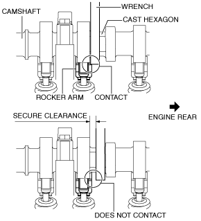
• If the camshaft is rotated with the timing chain removed and the piston at the top dead center position, the valve may contact the piston and the engine could be damaged. When rotating the camshaft with the timing chain removed, rotate it after lowering the piston from the top dead center position.
• When rotating the camshaft using a wrench on the cast hexagon, the wrench may contact the rocker arm and damage the rocker arm. To prevent damage to the rocker arm when holding the camshaft on the cast hexagon, use a wrench on the rear side of the engine as shown in the figure to secure a clearance between the cam.
-
Note
-
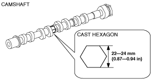
• Width at the cast hexagon of the camshaft is
22—24 mm {0.87—0.94 in}.
1. Disconnect the negative battery cable. (See NEGATIVE BATTERY CABLE DISCONNECTION/CONNECTION.)
2. Remove the seal cover. (See SEAL COVER REMOVAL/INSTALLATION [SKYACTIV-G 1.5, SKYACTIV-G 2.0].)
3. Remove the ignition coil/ion sensors. (See IGNITION COIL/ION SENSOR REMOVAL/INSTALLATION [SKYACTIV-G 1.5, SKYACTIV-G 2.0].)
4. Remove the air cleaner, air hose and resonance chamber No.1 as a single unit. (See INTAKE-AIR SYSTEM REMOVAL/INSTALLATION [SKYACTIV-G 1.5, SKYACTIV-G 2.0].)
5. Remove the drive belt. (See DRIVE BELT REMOVAL/INSTALLATION [SKYACTIV-G 1.5, SKYACTIV-G 2.0].)
6. Remove the front crossmember under cover. (See FRONT CROSSMEMBER UNDER COVER REMOVAL/INSTALLATION.)
7. Drain the engine oil. (See ENGINE OIL REPLACEMENT [SKYACTIV-G 1.5, SKYACTIV-G 2.0].)
8. Drain the engine coolant. (See ENGINE COOLANT REPLACEMENT [SKYACTIV-G 1.5, SKYACTIV-G 2.0].)
9. Remove the oil pan. (See OIL PAN REMOVAL/INSTALLATION [SKYACTIV-G 1.5, SKYACTIV-G 2.0].)
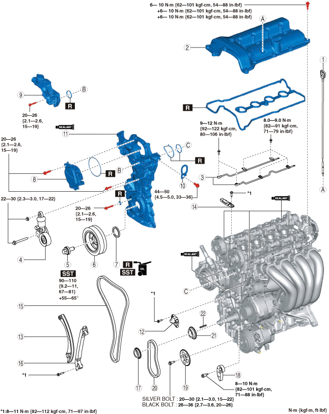
10. Remove in the order indicated in the table.
11. Install in the reverse order of removal.
12. Refill with the specified type and amount of the engine oil. (See ENGINE OIL REPLACEMENT [SKYACTIV-G 1.5, SKYACTIV-G 2.0].)
13. Refill the engine coolant. (See ENGINE COOLANT REPLACEMENT [SKYACTIV-G 1.5, SKYACTIV-G 2.0].)
14. Start the engine and inspect the following:
-
• Leakage of engine oil and engine coolant.
• Runout and contact of pulley and belt.
|
1
|
Dipstick
|
|
2
|
Cylinder head cover
|
|
3
|
Oil shower pipe
|
|
4
|
Drive belt auto tensioner
|
|
5
|
Crankshaft pulley lock bolt
|
|
6
|
Crankshaft pulley
|
|
7
|
Front oil seal
|
|
8
|
Electric variable valve timing motor/driver
|
|
9
|
Water outlet component
|
|
10
|
Engine hanger
|
|
11
|
Engine front cover
|
|
12
|
Chain tensioner
|
|
13
|
Tensioner arm
|
|
14
|
Chain guide (No.1)
|
|
15
|
Timing chain
|
|
16
|
Chain guide (No.2)
|
|
17
|
Crankshaft sprocket
|
|
18
|
Oil pump chain tensioner
|
|
19
|
Oil pump driven sprocket
|
|
20
|
Oil pump chain
|
|
21
|
Oil pump drive sprocket
|
|
22
|
Key
|
Cylinder Head Cover Removal Note
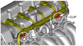
1. Disconnect the OCV connector.
2. Remove the wiring harness clip secured to the intake manifold as shown in the figure, and set the wiring harness aside.
3. Disconnect the ventilation hose.
4. Remove the cylinder head cover.
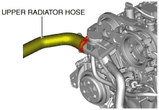
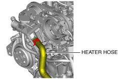
Water Outlet Component Removal Note
1. Disconnect the upper radiator hose.
2. Disconnect the heater hose.
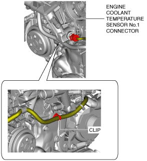
3. Set the engine coolant temperature sensor No.1 wiring harness aside using the following procedure:
- (1) Disconnect the engine coolant temperature sensor No.1 connector.
-
- (2) Remove the clip and set the wiring harness aside.
-
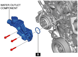
4. Remove the water outlet component.
Engine Front Cover Removal Note
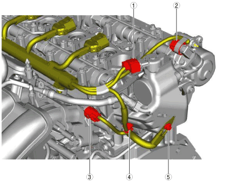
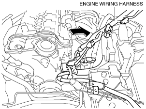
1. Set the engine wiring harness aside using the following procedure:
- (1) Disconnect the purge solenoid valve connector. (See PURGE SOLENOID VALVE REMOVAL/INSTALLATION [SKYACTIV-G 1.5, SKYACTIV-G 2.0].)
-
- (2) Disconnect or remove the following parts.
-
|
1
|
High pressure fuel pump connector
|
|
2
|
Exhaust camshaft position sensor connector
|
|
3
|
Intake camshaft position sensor connector
|
|
4
|
Wiring harness clip
|
|
5
|
Bolt
|
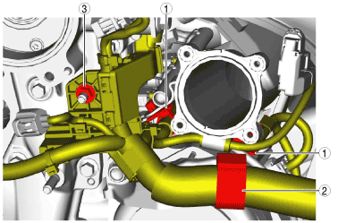
- (3) Remove the throttle body. (See INTAKE-AIR SYSTEM REMOVAL/INSTALLATION [SKYACTIV-G 1.5, SKYACTIV-G 2.0].)
-
- (4) Disconnect or remove the following parts.
-
Step 1
|
1
|
Wiring harness clip
|
|
2
|
Wiring harness clip
|
|
3
|
Wiring harness protector installation nut
|
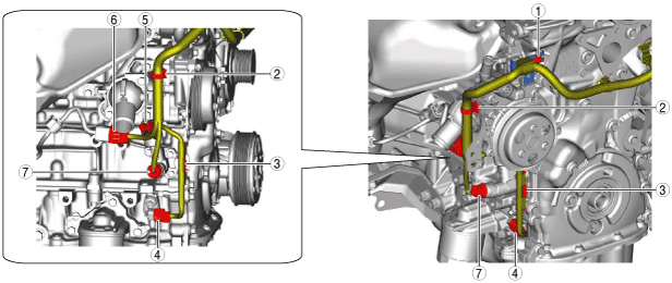
Step 2
|
1
|
Bolt
|
|
2
|
Wiring harness clip
|
|
3
|
Wiring harness clip
|
|
4
|
Crankshaft position (CKP) sensor connector
|
|
5
|
Engine oil solenoid valve connector
|
|
6
|
A/F sensor connector
|
|
7
|
Oil pressure switch connector
|
-
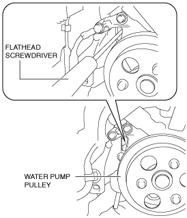
Note
-
• Remove the wiring harness clip next to the water pump by inserting a flathead screwdriver into the hole next to the water pump pulley as shown in the figure.
- (5) Set the engine wiring harness in a place which does not interfere with the servicing.
-
2. Remove the engine front cover installation bolts.
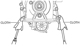
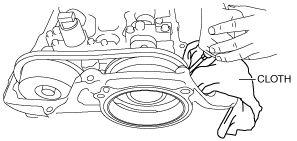
3. Using a screwdriver wrapped in a cloth, peel the silicone sealant away a little at a time, and remove the engine front cover.
-
Caution
-
• Do not apply excessive force to the screwdriver. Otherwise, the engine front cover could be damaged.
• Be careful not to scratch or damage the seal surface. Otherwise, it could cause oil leakage.
Timing Chain Removal Note
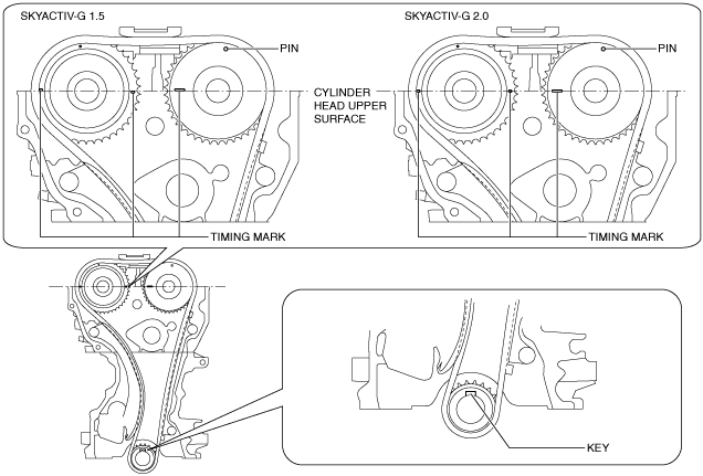
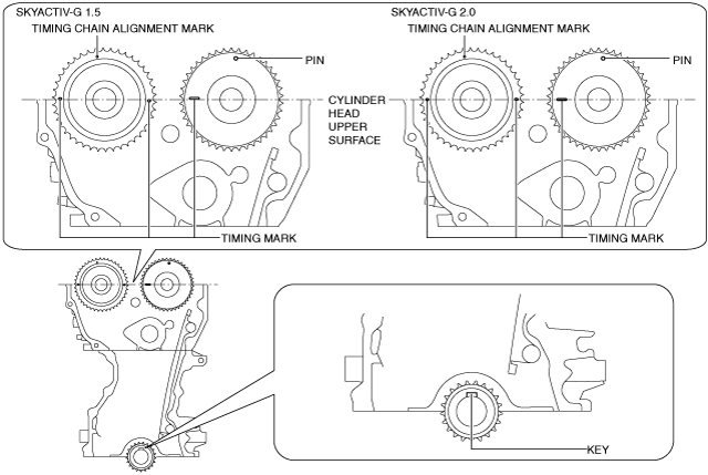
1. Rotate the crankshaft clockwise to align the timing marks and the key position as shown in the figure, and set cylinder No.1 at top dead center (TDC).
-
Note
-
• The timing mark of SKYACTIV-G 1.5 is not parallel with the upper surface of the cylinder head.
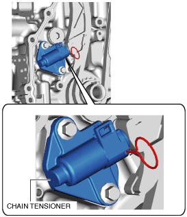
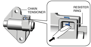
2. Loosen the chain tensioner using the following procedure:
- (1) Insert a metal rod (diameter approx. 1.4 mm {0.055 in}, length approx. 55 mm {2.2 in}) into the hole in the body of the chain tensioner.
-
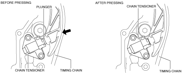
- (2) Press the resister ring and unlock the plunger.
-
- (3) Press the timing chain in the direction of the arrow and press in the chain tensioner plunger to the position where the groove and body hole are aligned.
-
- (4) With the plunger pressed in, further insert the metal rod set in (1) above.
-
-
Note
-
• The rod secures the plunger and releases the tension.
- (5) Loosen the power of the hand pressing the plunger and verify that the pressed-in rod does not move.
-
3. Remove the chain tensioner, tensioner arm, and the chain guide (No.1).
4. Remove the timing chain.
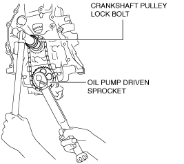
Oil Pump Driven Sprocket Removal Note
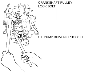
1. Temporarily assemble the crankshaft pulley lock bolt, and lock the oil pump against rotation as shown in the figure.
2. Remove the oil pump driven sprocket.
3. Remove the temporarily assembled crankshaft pulley lock bolt.
Oil Pump Driven Sprocket Installation Note
1. Temporarily assemble the crankshaft pulley lock bolt, and lock the oil pump against rotation as shown in the figure.
2. Install the oil pump driven sprocket.
-
Tightening torque
-
Silver bolt: 20—30 N·m {2.1—3.0 kgf·m, 15—22 ft·lbf}
Black bolt: 26—36 N·m {2.7—3.6 kgf·m, 20—26 ft·lbf}
3. Remove the temporarily assembled crankshaft pulley lock bolt.
Timing Chain Installation Note
1. Verify that the timing marks and the key are aligned to the position shown in the figure.
-
Note
-
• The timing mark of SKYACTIV-G 1.5 is not parallel with the upper surface of the cylinder head.
-
• If the timing marks and key position have deviated, align them to the positions shown in the figure.
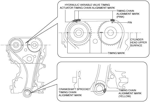
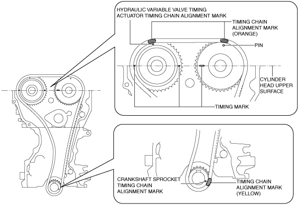
2. Install the timing chain while aligning the marks on the timing chain as shown in the figure.
SKYACTIV-G 1.5
SKYACTIV-G 2.0
3. Install the chain guide (No.1).
-
Tightening torque
-
8—11 N·m {82—112 kgf·cm, 71—97 in·lbf}
4. Install the tensioner arm.
5. Install the chain tensioner.
-
Tightening torque
-
8—11 N·m {82—112 kgf·cm, 71—97 in·lbf}
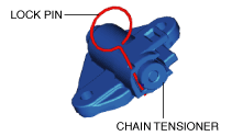
6. After installing the timing chain tensioner, remove the installed rod, and then apply tension to the timing chain.
-
• If a new chain tensioner is used, remove the installed lock pin.
7. Verify that there is no looseness in the timing chain, and re-verify that each sprocket is in the specified location.
8. Rotate the crankshaft clockwise two turns and inspect the valve timing.
-
Note
-
• The timing mark of SKYACTIV-G 1.5 is not parallel with the upper surface of the cylinder head.
Engine Front Cover Installation Note
-
Note
-
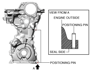
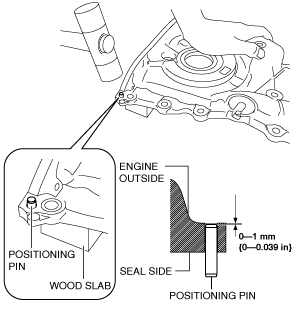
• For a new engine front cover, the positioning pins in the two locations shown in the figure project to the outside of the engine.
1. If the engine front cover is newly replaced, tap the positioning pins in the two locations to the seal surface side.
-
Caution
-
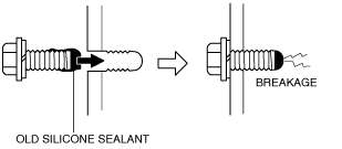
• If a bolt with silicone sealant adhering to it is used, it could result in cracks in the cylinder head and cylinder block.
2. When reusing an engine front cover installation bolts, remove silicone sealant adhering to the bolts.
-
Caution
-
• If oil, dirt and silicone sealant remains on the silicone sealant application area, the silicone sealant will not seal which will cause oil leakage.
3. Completely clean and remove oil, dirt, silicone sealant or other foreign matter that may be adhering to the engine front cover, cylinder head, and cylinder block.
-
Caution
-
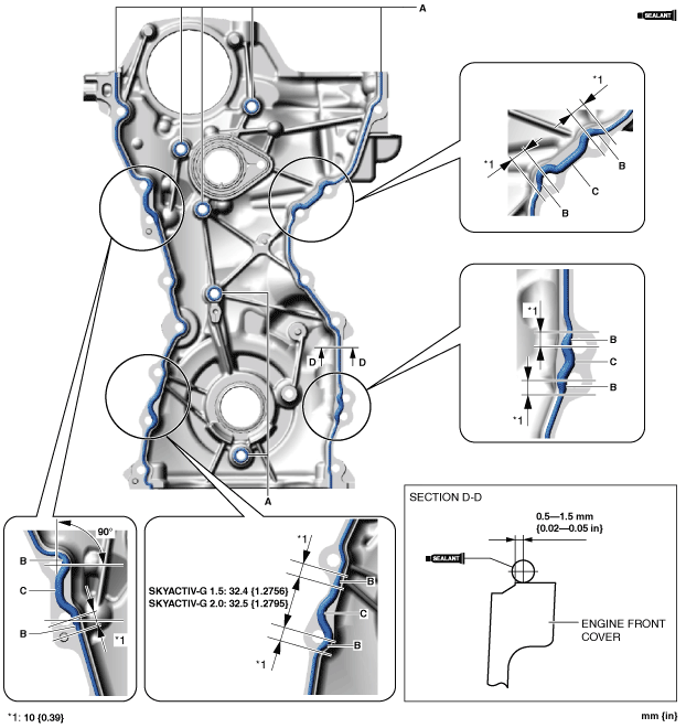
• Apply the silicon sealant in a single, unbroken line.
• To prevent silicone sealant from hardening, adhere the engine front cover and the cylinder block firmly within 10 min. after applying silicone sealant. After adhering them, tighten the installation bolts immediately.
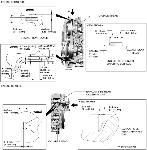
4. Apply silicone sealant (TB1217D or equivalent) to the engine front cover as shown in the figure.
-
Bead thickness
-
A: 2—6 mm {0.1—0.2 in}
B: 4—6 mm {0.16—0.23 in}
C: 4—8 mm {0.2—0.3 in}
-
Caution
-
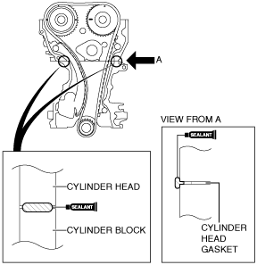
• Apply the silicone sealant so that it goes into the cylinder head gasket.
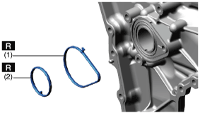
5. Apply silicone sealant (TB1217D or equivalent) to the areas shown in the figure.
-
Caution
-
• Do not apply engine coolant to the O-ring (1). Otherwise, the O-ring could swell causing a seal malfunction.
• Do not apply oil (such as engine oil, ATF) to the O-ring (2). Otherwise, the O-ring could swell causing a seal malfunction.
6. Install a new O-ring to the O-ring installation groove of the engine front cover.
7. Install the engine front cover to the engine.
-
Note
-
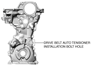
• Temporarily install an appropriate bolt to the drive belt auto tensioner installation bolt hole to prevent:
-
― A silicone sealant adhesion malfunction in the drive belt auto tensioner installation bolt hole.
― A bolt mis-installation due to silicone sealant hardening.
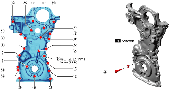
8. Prepare an appropriate M8 × 1.25 bolt (length 40 mm {1.6 in}).
-
Caution
-
• For the number 3 bolt of the tightening order, install the bolt with new washer.
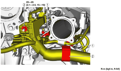
9. Tighten the engine front cover installation bolts in the order shown in the figure.
-
Tightening torque
-
20—26 N·m {2.1—2.6 kgf·m, 15—19 ft·lbf}
10. Remove the bolt installed to the drive belt auto tensioner installation bolt hole when installing the drive belt auto tensioner.
11. Return the engine wiring harness to its original position using the following procedure.
- (1) Connect or install the following parts.
-
Step 1
|
1
|
Bolt
|
|
2
|
Wiring harness clip
|
|
3
|
Wiring harness clip
|
|
4
|
Crankshaft position (CKP) sensor connector
|
|
5
|
Engine oil solenoid valve connector
|
|
6
|
A/F sensor connector
|
|
7
|
Oil pressure switch connector
|
Step 2
|
1
|
Wiring harness clip
|
|
2
|
Wiring harness clip
|
|
3
|
Wiring harness protector installation nut
|
- (2) Install the throttle body. (See INTAKE-AIR SYSTEM REMOVAL/INSTALLATION [SKYACTIV-G 1.5, SKYACTIV-G 2.0].)
-
- (3) Connect or install the following parts.
-
|
1
|
High pressure fuel pump connector
|
|
2
|
Exhaust camshaft position sensor connector
|
|
3
|
Intake camshaft position sensor connector
|
|
4
|
Wiring harness clip
|
|
5
|
Bolt
|
- (4) Connect the purge solenoid valve connector. (See PURGE SOLENOID VALVE REMOVAL/INSTALLATION [SKYACTIV-G 1.5, SKYACTIV-G 2.0].)
-
Water Outlet Component Installation Note
-
Caution
-
• Do not apply oil (such as engine oil, ATF) to the gasket. Otherwise, the gasket could swell causing a seal malfunction.
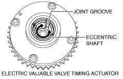
Electric Variable Valve Timing Motor/Driver Installation Note
1. Install a new O-ring to the O-ring installation groove of the engine front cover.
-
Caution
-
• To prevent damage to the electric variable valve timing motor/driver, do not apply excessive force (force of 100 N {10.2 kgf, 22.5 lbf} or more) to the shaded areas shown in the figure.
2. Install the electric variable valve timing motor/driver using the following procedures.
-
Note
-
• The eccentric shaft on the electric variable valve timing actuator side can be rotated to the left and right.
• The electric variable valve timing motor/driver can be assembled with the joint groove of the eccentric shaft in any position, and it will not lead to vehicle damage or performance reduction.
- (1) Before installation, rotate the joint on the end of the electric variable valve timing motor/driver so that it is aligned to the joint groove on the electric variable valve timing actuator side.
-
- (2) Engage the joint on the end of the electric variable valve timing motor/driver with the joint groove on the electric variable valve timing actuator side.
-
- (3) Attach the seal surface.
-
- (4) Tighten the electric variable valve timing motor/driver installation bolts.
-
-
Tightening torque
-
20—26 N·m {2.1—2.6 kgf·m, 15—19 ft·lbf}
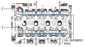
Oil Shower Pipe Installation Note
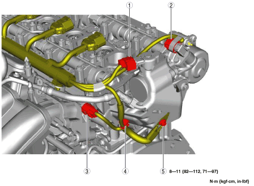
1. Install the oil shower pipe in the order shown in the figure.
Tightening torque
|
Installation position
|
Tightening torque
|
|
1
|
9—12 N·m {92—122 kgf·cm, 80—106 in·lbf}
|
|
2, 3
|
8.0—9.0 N·m {82—91 kgf·cm, 71—79 in·lbf}
|
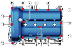
Cylinder Head Cover Installation Note
-
Caution
-
• To assure the sealing performance of the cylinder head cover, be careful of the following:
-
― Verify that the cylinder head cover gasket is inserted into the cylinder head cover groove and install the cylinder head cover.
― Completely clean and remove oil, dirt, silicone sealant or other foreign matter from the seal surface.
• To prevent silicone sealant from hardening, adhere the cylinder head cover and the cylinder head firmly within 10 min. after applying silicone sealant. After adhering them, tighten the installation bolts immediately.
1. Insert a new cylinder head cover gasket into the cylinder head cover groove.
2. Apply silicone sealant (TB1217D or equivalent) to the areas shown in the figure.
3. Tighten the cylinder head cover bolts in the order shown in the following 3 steps.
-
Tightening torque
-
Step 1: 6—10 N·m {62—101 kgf·cm, 54—88 in·lbf}
Step 2: 6—10 N·m {62—101 kgf·cm, 54—88 in·lbf}
Step 3: 6—10 N·m {62—101 kgf·cm, 54—88 in·lbf}
4. Measure the tightening torque again and verify that it is 6 N·m {62 kgf·cm, 54 in·lbf} or more.
5. Install in the reverse order of removal.