 |
amxuuw00004743
WHEEL HUB COMPONENT REMOVAL/INSTALLATION
id031200800400
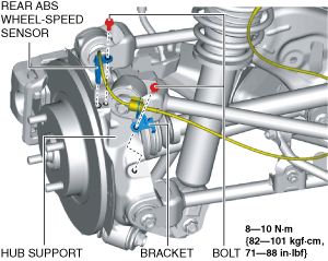
1. Remove the rear ABS wheel-speed sensor and bracket from the hub support, and set it aside so that it does not interfere with the servicing.
amxuuw00004743
|
2. Remove the rear brake caliper component and suspend it in a place out of the way using a cable. (See REAR BRAKE DISC REMOVAL/INSTALLATION.)
amxuuw00004744
|
3. Remove the rear disc plate. (See REAR BRAKE DISC REMOVAL/INSTALLATION.)
4. When working on the left side of the vehicle, disconnect the auto leveling sensor link from the lower lateral link. (With auto leveling sensor) (See AUTO LEVELING SENSOR REMOVAL/INSTALLATION.)
5. Disconnect the rear stabilizer control link from the lower lateral link. (With rear stabilizer) (See REAR STABILIZER REMOVAL/INSTALLATION.)
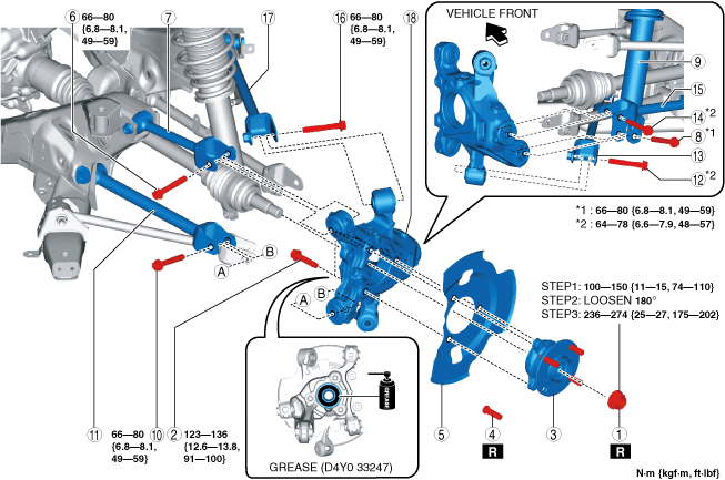
6. Remove in the order shown in the figure.
7. Install in the reverse order of removal.
8. Inspect the rear wheel alignment and adjust if necessary. (See REAR WHEEL ALIGNMENT.)
amxzzw00005847
|
|
1
|
Locknut
(See Locknut Removal Note.)
(See Locknut Installation Note.)
|
|
2
|
Bolt
|
|
3
|
Wheel hub component
|
|
4
|
Rear wheel hub bolt
|
|
5
|
Dust cover
|
|
6
|
Bolt
(See Bolt Installation Note.)
|
|
7
|
Upper lateral link
|
|
8
|
Bolt
|
|
9
|
Rear shock absorber and coil spring
|
|
10
|
Bolt
(See Bolt Installation Note.)
|
|
11
|
Lower link
|
|
12
|
Bolt
|
|
13
|
Trailing link
|
|
14
|
Bolt
|
|
15
|
Lower lateral link
|
|
16
|
Bolt
|
|
17
|
Leading link
|
|
18
|
Hub support
|
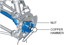
Locknut Removal Note
1. Remove the locknut with the brake pedal depressed.
2. After removing the locknut, temporarily install a nut to the end of the rear drive shaft.
3. Tap the nut with a copper hammer and separate the rear drive shaft from the axle.
amxuuw00004746
|
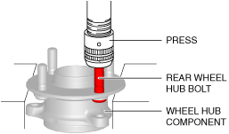
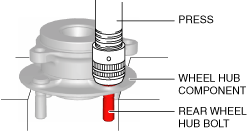
Rear Wheel Hub Bolt Removal Note
1. Remove the rear wheel hub bolt from the wheel hub component using a press.
amxuuw00004747
|
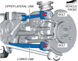
Bolt Installation Note
1. Completely tighten the bolts shown in the figure to the specified torque with the vehicle lifted up.
amxuuw00004748
|
Rear Wheel Hub Bolt Installation Note
1. Press in new rear wheel hub bolt into the wheel hub component using a press.
amxuuw00004749
|
Wheel Hub Component Installation Note
1. Apply grease (D4Y0 33247) to the wheel bearing inner race and rear drive shaft contact surfaces (area A in the figure).
amxuuw00004750
|
2. Install the wheel hub component.
Locknut Installation Note
1. If dust or grease is on the drive shaft thread area, wipe it off with a cloth.
2. Tighten the locknut using the following procedure and with the brake pedal depressed.