 |
amxuuw00002845
ELECTRIC AT OIL PUMP INSPECTION [SJ6A-EL]
id051311500800
1. Disconnect the negative battery cable. (See NEGATIVE BATTERY CABLE DISCONNECTION/CONNECTION.)
2. Remove the selector lever knob. (See AUTOMATIC TRANSMISSION SHIFT MECHANISM REMOVAL/INSTALLATION.)
3. Remove the shift panel component. (See SHIFT PANEL REMOVAL/INSTALLATION.)
4. Remove the upper panel. (See UPPER PANEL REMOVAL/INSTALLATION.)
5. Remove the parking brake lever boot panel. (See PARKING BRAKE LEVER BOOT PANEL REMOVAL/INSTALLATION.)
6. Remove the rear console. (See REAR CONSOLE REMOVAL/INSTALLATION.)
7. Remove the front console panel. (See FRONT CONSOLE PANEL REMOVAL/INSTALLATION.)
8. Remove the front console component. (See FRONT CONSOLE REMOVAL/INSTALLATION.)
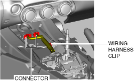
9. Disconnect the connector and wiring harness clip.
amxuuw00002845
|
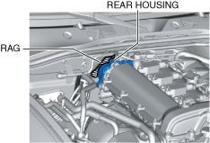
10. Place a clean rag behind the engine so that the engine does not contact the rear housing when it is tilted.
amxuuw00004812
|
11. Remove the front crossmember under cover. (See FRONT CROSSMEMBER UNDER COVER REMOVAL/INSTALLATION.)
12. Disconnect the control rod from the selector lever component. (See AUTOMATIC TRANSMISSION SHIFT MECHANISM REMOVAL/INSTALLATION.)
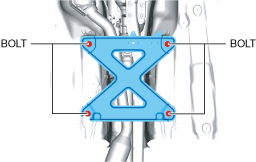
13. Remove the tunnel member.
amxuuw00003817
|
14. Disconnect the HO2S connector. (See HEATED OXYGEN SENSOR (HO2S) REMOVAL/INSTALLATION [SKYACTIV-G 1.5, SKYACTIV-G 2.0].)
15. Disconnect the TWC from the exhaust manifold (WU-TWC). (See EXHAUST SYSTEM REMOVAL/INSTALLATION [SKYACTIV-G 1.5, SKYACTIV-G 2.0].)
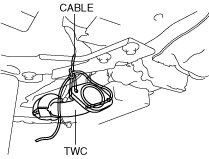
16. Suspend the TWC using a cable as shown in the figure.
amxuuw00002847
|
17. Remove the power plant frame. (See POWER PLANT FRAME REMOVAL [M66M-D].)
18. Tilt the transmission while being careful not to allow parts on the back of the engine to contact the vehicle body.
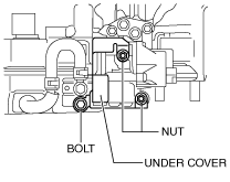
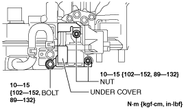
19. Remove the under cover.
amxzzw00003346
|
20. Install the power plant frame. (See POWER PLANT FRAME INSTALLATION [M66M-D].)
21. Install the TWC to the exhaust manifold (WU-TWC). (See EXHAUST SYSTEM REMOVAL/INSTALLATION [SKYACTIV-G 1.5, SKYACTIV-G 2.0].)
22. Connect the HO2S connector. (See HEATED OXYGEN SENSOR (HO2S) REMOVAL/INSTALLATION [SKYACTIV-G 1.5, SKYACTIV-G 2.0].)
23. Install the control rod from the selector lever component. (See AUTOMATIC TRANSMISSION SHIFT MECHANISM REMOVAL/INSTALLATION.)
24. Remove the cloth from the rear side of the engine.
amxuuw00004812
|
25. Connect the connector and wiring harness clip.
amxuuw00002845
|
26. Install the front console component. (See FRONT CONSOLE REMOVAL/INSTALLATION.)
27. Install the front console panel. (See FRONT CONSOLE PANEL REMOVAL/INSTALLATION.)
28. Install the rear console. (See REAR CONSOLE REMOVAL/INSTALLATION.)
29. Install the parking brake lever boot panel. (See PARKING BRAKE LEVER BOOT PANEL REMOVAL/INSTALLATION.)
30. Install the upper panel. (See UPPER PANEL REMOVAL/INSTALLATION.)
31. Install the shift panel component. (See SHIFT PANEL REMOVAL/INSTALLATION.)
32. Connect the negative battery cable. (See NEGATIVE BATTERY CABLE DISCONNECTION/CONNECTION.)
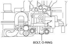
33. Remove the bolt and O-ring from the hydraulic pressure detection port.
amxzzw00003347
|
34. Drain leaked ATF.
35. Install the SSTs (49 D019 910, 49 D019 911, 49 D019 913, 49 D019 909, 49 D019 908) to the hydraulic pressure detection port as shown in the figure.
amxzzw00003348
|
36. Connect the M-MDS to the DLC-2.
37. After vehicle identification is completed, select the following from the M-MDS initial screen.
38. Verify the ATF temperature using the PID/data monitor "TFT".
39. Warm up the engine until the ATF temperature is 55—65 °C {99—117 °F}.
40. Select “EOP" from the PID/DATA Monitor Table.
41. Verify that the operation hydraulic pressure of the electric AT oil pump is within the standard when simulation item “EOP" is performed.
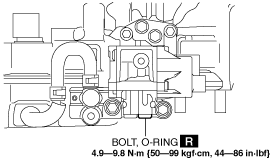
42. Remove the SSTs and install the bolt and a new O-ring to the hydraulic pressure detection port.
amxzzw00003349
|
43. Completely remove any remaining ATF from the area around the transmission and spacer.
44. Disconnect the negative battery cable. (See NEGATIVE BATTERY CABLE DISCONNECTION/CONNECTION.)
45. Remove the shift panel component. (See SHIFT PANEL REMOVAL/INSTALLATION.)
46. Remove the upper panel. (See UPPER PANEL REMOVAL/INSTALLATION.)
47. Remove the parking brake lever boot panel. (See PARKING BRAKE LEVER BOOT PANEL REMOVAL/INSTALLATION.)
48. Remove the rear console. (See REAR CONSOLE REMOVAL/INSTALLATION.)
49. Remove the front console panel. (See FRONT CONSOLE PANEL REMOVAL/INSTALLATION.)
50. Remove the front console component. (See FRONT CONSOLE REMOVAL/INSTALLATION.)
51. Disconnect the connector and wiring harness clip.
amxuuw00002845
|
52. Place a clean rag behind the engine so that the engine does not contact the rear housing when it is tilted.
amxuuw00004812
|
53. Disconnect the control rod from the selector lever component. (See AUTOMATIC TRANSMISSION SHIFT MECHANISM REMOVAL/INSTALLATION.)
54. Disconnect the HO2S connector. (See HEATED OXYGEN SENSOR (HO2S) REMOVAL/INSTALLATION [SKYACTIV-G 1.5, SKYACTIV-G 2.0].)
55. Disconnect the TWC from the exhaust manifold (WU-TWC). (See EXHAUST SYSTEM REMOVAL/INSTALLATION [SKYACTIV-G 1.5, SKYACTIV-G 2.0].)
56. Suspend the TWC using a cable as shown in the figure.
amxuuw00002847
|
57. Remove the power plant frame. (See POWER PLANT FRAME INSTALLATION [M66M-D].)
58. Tilt the transmission while being careful not to allow parts on the back of the engine to contact the vehicle body.
59. Install the under cover.
amxzzw00003350
|
60. Install the power plant frame. (See POWER PLANT FRAME INSTALLATION [M66M-D].)
61. Remove the tunnel member temporarily.
amxuuw00003817
|
62. Install the TWC to the exhaust manifold (WU-TWC). (See EXHAUST SYSTEM REMOVAL/INSTALLATION [SKYACTIV-G 1.5, SKYACTIV-G 2.0].)
63. Connect the HO2S connector. (See HEATED OXYGEN SENSOR (HO2S) REMOVAL/INSTALLATION [SKYACTIV-G 1.5, SKYACTIV-G 2.0].)
64. Install the tunnel member.
amxuuw00003818
|
65. Install the control rod from the selector lever component. (See AUTOMATIC TRANSMISSION SHIFT MECHANISM REMOVAL/INSTALLATION.)
66. Install the front crossmember under cover. (See FRONT CROSSMEMBER UNDER COVER REMOVAL/INSTALLATION.)
67. Connect the connector and wiring harness clip.
amxuuw00002845
|
68. Install the front console component. (See FRONT CONSOLE REMOVAL/INSTALLATION.)
69. Install the front console panel. (See FRONT CONSOLE PANEL REMOVAL/INSTALLATION.)
70. Install the rear console. (See REAR CONSOLE REMOVAL/INSTALLATION.)
71. Install the parking brake lever boot panel. (See PARKING BRAKE LEVER BOOT PANEL REMOVAL/INSTALLATION.)
72. Install the upper panel. (See UPPER PANEL REMOVAL/INSTALLATION.)
73. Install the shift panel component. (See SHIFT PANEL REMOVAL/INSTALLATION.)
74. Install the selector lever knob. (See AUTOMATIC TRANSMISSION SHIFT MECHANISM REMOVAL/INSTALLATION.)
75. Connect the negative battery cable. (See NEGATIVE BATTERY CABLE DISCONNECTION/CONNECTION.)
76. If the amount of ATF leakage is 0.15 L {0.16 US qt, 0.13 Imp qt} or more (reference), adjust the ATF amount. (See AUTOMATIC TRANSMISSION FLUID (ATF) LEVEL ADJUSTMENT [SJ6A-EL].)