ELECTRICAL SUPPLY UNIT (ESU) REMOVAL/INSTALLATION
id094000003200
L.H.D.
1. Disconnect the negative battery cable. (See NEGATIVE BATTERY CABLE DISCONNECTION/CONNECTION.)
2. Remove the following parts:
- (1) Selector lever knob (AT) (See AUTOMATIC TRANSMISSION SHIFT MECHANISM REMOVAL/INSTALLATION.)
- (2) Shift lever knob (MT)
- (3) Shift panel component (See SHIFT PANEL REMOVAL/INSTALLATION.)
- (4) Upper panel (See UPPER PANEL REMOVAL/INSTALLATION.)
- (5) Parking brake lever boot panel (See PARKING BRAKE LEVER BOOT PANEL REMOVAL/INSTALLATION.)
- (6) Rear console (See REAR CONSOLE REMOVAL/INSTALLATION.)
- (7) Front console panel (See FRONT CONSOLE PANEL REMOVAL/INSTALLATION.)
- (8) Front console component (See FRONT CONSOLE REMOVAL/INSTALLATION.)
- (9) Seat (driver's side) (See SEAT REMOVAL/INSTALLATION.)
- (10) Scuff plate (driver's side) (See SCUFF PLATE REMOVAL/INSTALLATION.)
- (11) Tire house trim (driver's side) (See TIRE HOUSE TRIM REMOVAL/INSTALLATION.)
- (12) Seat belt lower anchor installation bolt (driver's side) (without lap pre-tensioner seat belts) (See SEAT BELT REMOVAL/INSTALLATION.)
- (13) Lap pre-tensioner lower anchor cover (driver's side) (with lap pre-tensioner seat belts) (See SEAT BELT REMOVAL/INSTALLATION.)
- (14) Lap pre-tensioner lower anchor installation bolt (driver's side) (with lap pre-tensioner seat belts) (See SEAT BELT REMOVAL/INSTALLATION.)
- (15) Accelerator pedal (See ACCELERATOR PEDAL REMOVAL/INSTALLATION [SKYACTIV-G 1.5, SKYACTIV-G 2.0].)
3. Pull back the floor covering to a position which allows for the removal of the electrical supply unit (ESU). (See FLOOR COVERING REMOVAL/INSTALLATION.)
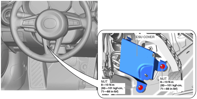
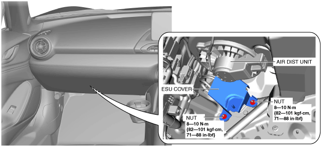
4. Remove the nuts.
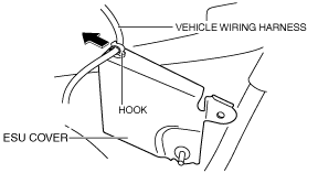
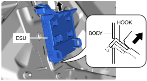
5. Remove the vehicle wiring harness from the hook by pulling it in the direction of the arrow.
6. Remove the electrical supply unit (ESU) cover.
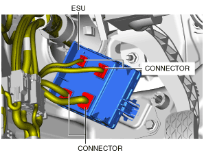
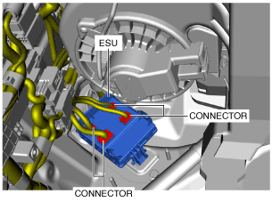
7. Disconnect the connectors.
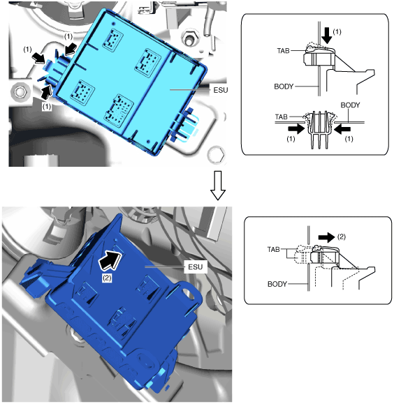
8. While pressing the tabs of the electrical supply unit (ESU) in the direction of arrow (1) shown in the figure simultaneously, pull them in the direction of arrow (2) to detach the tabs from the body.
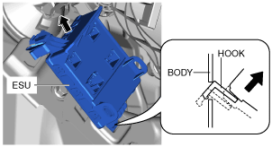
9. Pull the electrical supply unit (ESU) in the direction of the arrow shown in the figure and detach the hook from the body.
10. Remove the electrical supply unit (ESU).
11. Install in the reverse order of removal.
R.H.D.
1. Disconnect the negative battery cable. (See NEGATIVE BATTERY CABLE DISCONNECTION/CONNECTION.)
2. Remove the following parts:
- (1) Scuff plate (passenger's side) (See SCUFF PLATE REMOVAL/INSTALLATION.)
- (2) Front side trim (passenger's side) (See FRONT SIDE TRIM REMOVAL/INSTALLATION.)
- (3) A-pillar trim (passenger's side) (See A-PILLAR TRIM REMOVAL/INSTALLATION.)
- (4) Passenger-side lower panel (See PASSENGER-SIDE LOWER PANEL REMOVAL/INSTALLATION.)
- (5) Selector lever knob (AT) (See AUTOMATIC TRANSMISSION SHIFT MECHANISM REMOVAL/INSTALLATION.)
- (6) Shift lever knob (MT)
- (7) Shift panel compartment (See SHIFT PANEL REMOVAL/INSTALLATION.)
- (8) Upper panel (See UPPER PANEL REMOVAL/INSTALLATION.)
- (9) Parking brake lever boot panel (See PARKING BRAKE LEVER BOOT PANEL REMOVAL/INSTALLATION.)
- (10) Rear console (See REAR CONSOLE REMOVAL/INSTALLATION.)
- (11) Front console panel (See FRONT CONSOLE PANEL REMOVAL/INSTALLATION.)
- (12) Front console compartment (See FRONT CONSOLE REMOVAL/INSTALLATION.)
- (13) Front cup holder bracket (See FRONT CUP HOLDER BRACKET REMOVAL/INSTALLATION.)
- (14) Foot support (See FOOT SUPPORT REMOVAL/INSTALLATION.)
- (15) Woofer (See WOOFER REMOVAL/INSTALLATION.)
3. Remove the nut.
4. Remove the vehicle wiring harness from the hook by pulling it in the direction of the arrow.
5. Remove the electrical supply unit (ESU) cover.
6. Disconnect the connectors.
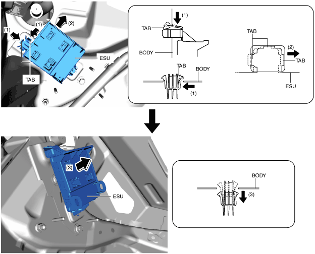
7. While pressing the electrical supply unit (ESU) tabs in the direction of arrow (1) shown in the figure simultaneously, slide them in the direction of arrow (2), and then pull them in the direction of arrow (3) to detach them from the body.
8. Pull the electrical supply unit (ESU) in the direction of the arrow shown in the figure and detach the hook from the body.
9. Remove the electrical supply unit (ESU).
10. Install in the reverse order of removal.