 |
bcw6ja00000250
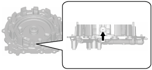
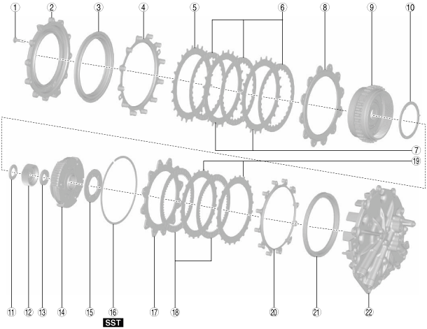
END COVER COMPONENT DISASSEMBLY
id051700661200
Structural view
bcw6ja00000250
|
|
1
|
8 bolts
|
|
2
|
Brake housing
|
|
3
|
2-6 brake piston
|
|
4
|
Springs and retainer component
|
|
5
|
Retaining plate
|
|
6
|
Drive plate
|
|
7
|
Driven plate
|
|
8
|
Retaining plate
|
|
9
|
Rear internal gear and reduction internal gear component
|
|
10
|
Thrust washer
|
|
11
|
Thrust needle bearing
|
|
12
|
Reduction sun gear
|
|
13
|
Thrust needle bearing
|
|
14
|
Reduction planetary gear
|
|
15
|
Thrust washer
|
|
16
|
Snap ring
|
|
17
|
Retaining plate
|
|
18
|
Drive plate
|
|
19
|
Driven plate
|
|
20
|
Springs and retainer component
|
|
21
|
R-3-5 brake piston
|
|
22
|
End cover
|
Disassembly Procedure
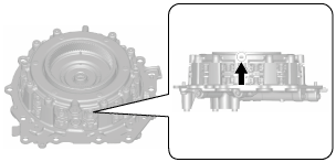
1. Perform a simple inspection of the 2-6 brake using the following procedure:
bcw6ja00000251
|
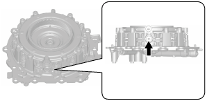
2. Perform a simple inspection of the R-3-5 brake using the following procedure:
bcw6ja00000252
|
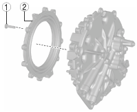
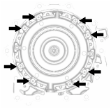
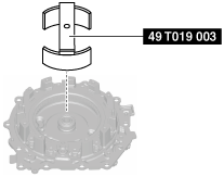
3. Remove the brake housing using the following procedure:
bcw6ja00000253
|
|
1
|
8 bolts
|
|
2
|
Brake housing
|
bcw6ja00000254
|
bcw6ja00000255
|
4. Remove the 2-6 brake piston from the brake housing using the following procedure:
bcw6ja00000256
|
bcw6ja00000257
|
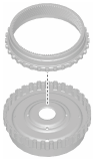
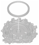
5. Remove the springs and retainer component.
bcw6ja00000258
|
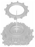
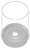
6. Remove the retaining plate.
bcw6ja00000259
|
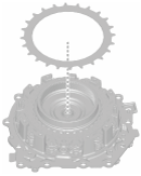
7. Remove the drive plates and driven plates.
bcw6ja00000028
|
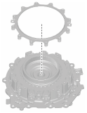
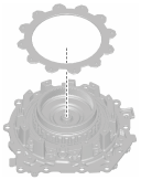
8. Remove the retaining plate.
bcw6ja00000260
|
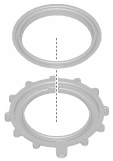
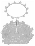
9. Remove the rear internal gear and reduction internal gear component.
bcw6ja00000026
|
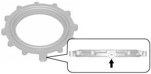
10. Remove the reduction internal gear from the rear internal gear and reduction internal gear component using the following procedure:
bcw6ja00000261
|
bcw6ja00000262
|
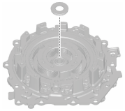
11. Remove the thrust washer.
bcw6ja00000263
|
12. Remove the thrust needle bearing.
bcw6ja00000264
|
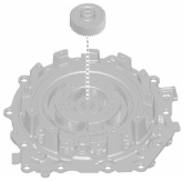
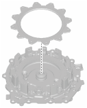
13. Remove the reduction sun gear.
bcw6ja00000265
|
14. Remove the thrust needle bearing.
bcw6ja00000266
|
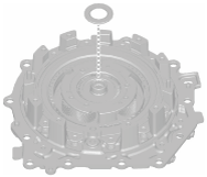
15. Remove the reduction planetary gear.
bcw6ja00000267
|
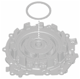
16. Remove the thrust washer.
bcw6ja00000268
|
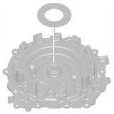
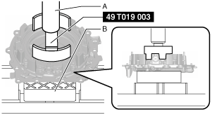
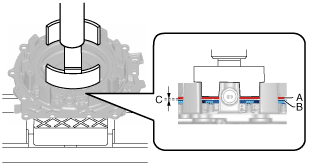
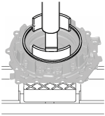
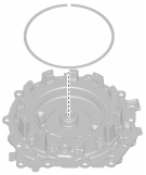
17. Remove the snap ring using the following procedure:
bcw6ja00000050
|
bcw6ja00000051
|
bcw6ja00000648
|
bcw6ja00000649
|
bcw6ja00000650
|
bcw6ja00000053
|
bcw6ja00000054
|
bcw6ja00000269
|
18. Remove the retaining plate.
bcw6ja00000270
|
19. Remove the drive plates and driven plates.
bcw6ja00000055
|
20. Remove the springs and retainer component.
bcw6ja00000271
|
21. Remove the R-3-5 brake piston using the following procedure:
bcw6ja00000272
|
bcw6ja00000273
|
22. Clean the disassembled parts. (See AUTOMATIC TRANSAXLE CLEANING.)
23. Perform the following inspection and replace a malfunctioning part with a new one.