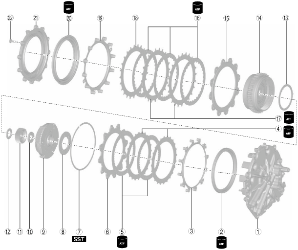
END COVER COMPONENT ASSEMBLY
id051700664200
Structural view
|
1
|
End cover
|
|
2
|
R-3-5 brake piston
|
|
3
|
Springs and retainer component (inner diameter approx. 153.4 mm {6.039 in})
|
|
4
|
Driven plate (inner diameter approx. 132.2 mm {5.205 in})
|
|
5
|
Drive plate (outer diameter approx. 159.8 mm {6.291 in})
|
|
6
|
Retaining plate (inner diameter approx. 132.2 mm {5.205 in})
|
|
7
|
Snap ring (outer diameter approx. 174.2 mm {6.858 in}) (selection)
|
|
8
|
Thrust washer (inner diameter approx. 46 mm {1.8 in})
|
|
9
|
Reduction planetary gear
|
|
10
|
Thrust needle bearing (inner diameter approx. 18.5 mm {0.728 in})
|
|
11
|
Reduction sun gear
|
|
12
|
Thrust needle bearing (outer diameter approx. 38 mm {1.5 in})
|
|
13
|
Thrust washer (outer diameter approx. 87.7 mm {3.45 in})
|
|
14
|
Rear internal gear and reduction internal gear component
|
|
15
|
Retaining plate (inner diameter approx. 137.2 mm {5.402 in}) (selection)
|
|
16
|
Drive plate (outer diameter approx. 160.4 mm {6.315 in})
|
|
17
|
Driven plate (outer diameter approx. 137.2 mm {5.402 in}, thickness 1.6 mm {0.063 in})
|
|
18
|
Retaining plate (inner diameter approx. 137.2 mm {5.402 in})
|
|
19
|
Springs and retainer component (inner diameter approx. 150.4 mm {5.921 in})
|
|
20
|
2-6 brake piston
|
|
21
|
Brake housing
|
|
22
|
8 Bolts (M6 x 1.0 bolt, length approx. 25 mm {0.98 in})
|
Assembly Procedure
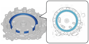
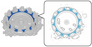
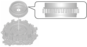
1. Assemble the R-3-5 brake piston using the following procedure:
- (1) Apply ATF (ATF FZ) to the R-3-5 brake piston lip.
- (2) Assemble the R-3-5 brake piston.
-
2. Measure the R-3-5 brake clearance and select the appropriate snap ring. (See R-3-5 BRAKE CLEARANCE MEASUREMENT/ADJUSTMENT.)
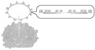
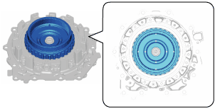
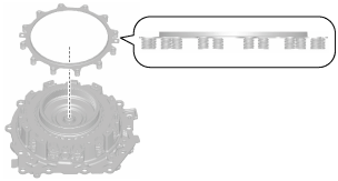
3. Assemble the springs and retainer component.
-
Note
-
• Springs and retainer component size: Inner diameter approx. 153.4 mm {6.039 in}
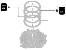
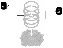
4. Assemble the drive plates and driven plates using the following procedure:
-
Note
-
• Drive plate size: Outer diameter approx. 159.8 mm {6.291 in}
• Driven plate size: Inner diameter approx. 132.2 mm {5.205 in}
- (1) Apply ATF (ATF FZ) to the drive plates and driven plates.
-
-
Caution
-
• If the drive plate is replaced with a new one, immerse it in ATF (ATF FZ) for 2 h or more to permeate the facing with ATF.
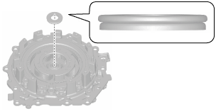
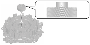
- (2) Assemble the drive plates and driven plates.
-
-
Assembly order
-
Driven plate—drive plate—driven plate—drive plate
A :Drive plate
B :Driven plate
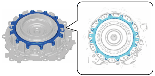
5. Assemble the retaining plate.
-
Note
-
• Retaining plate size: Inner diameter approx. 132.2 mm {5.205 in}
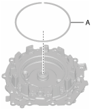
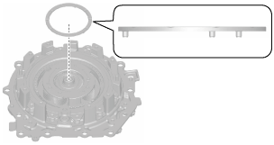
6. Assemble the snap ring using the following procedure:
-
Note
-
• Snap ring size: Outer diameter approx. 174.2 mm {6.858 in}
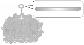
- (1) Set the snap ring selected in Step 2 on top of the end cover.
-
A :Selection
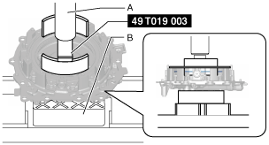
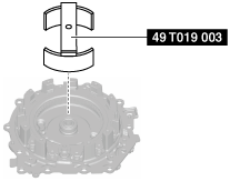
- (2) Install the SST.
-
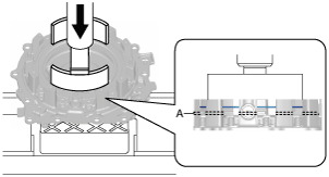
- (3) Set the SST and part to the press as shown in the figure.
-
-
Caution
-
• Using the rubber plates, adjust the alignment surface of the end cover with the transaxle case so that it is level. Otherwise the parts could tip over during the procedure and get damaged.
A :Press
B :Rubber plate
- (4) Press down the SST using the press until the snap ring groove of the end cover comes out.
-
-
Caution
-
• If the SST is pressed excessively by the press, surrounding parts could be damaged. Stop pressing down the SST using the press when the snap ring groove of the end cover comes out.
A :Snap ring groove
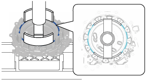
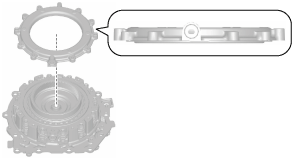
- (5) Assemble the snap ring to the position shown in the figure.
-
-
Caution
-
• After assembling the snap ring, verify that the snap ring is securely inserted into the bottom of the snap ring groove.
- (6) Take the SST and part off the press.
-
- (7) Remove the SST.
-
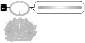
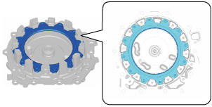
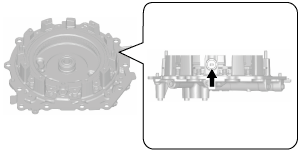
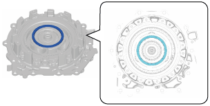
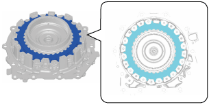
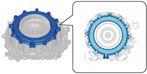
7. Perform an operation verification of the R-3-5 brake using the following procedure:
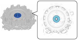
- (1) Blow compressed air into the oil passage shown in the figure and verify the operation condition of the R-3-5 brake.
-
-
Warning
-
• Always wear protective eye wear when using the air compressor. Otherwise, ATF or dirt particles blown off by the air compressor could get into the eyes.
-
Caution
-
• To prevent damage to parts, always use an air compressor which is adjusted to the indicated pressure.
-
Compressed air pressure
-
0.39—0.44 MPa {4.0—4.4 kgf/cm2, 57—63 psi}
-
8. Assemble the thrust washer.
-
Note
-
• Thrust washer size: Inner diameter approx. 137.2 mm {5.402 in}
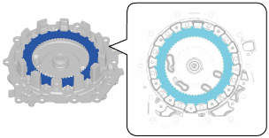
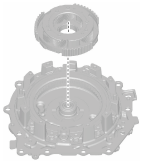
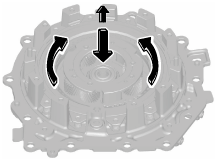
9. Assemble the reduction planetary gear.
-
Note
-
• While rotating the reduction planetary gear, engage the splines of each of the R-3-5 brake drive plates one by one, and assemble.
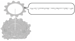
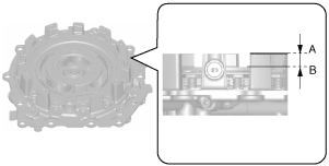
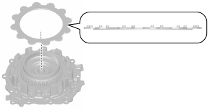
10. To verify that the reduction planetary gear is securely assembled, measure the distance shown in the figure.
-
Note
-
• Recommended measuring instrument: Depth gauge, straight edge ruler
A :End cover end (alignment surface with brake housing)
B :Reduction planetary carrier
-
Specification
-
24.5—25.2 mm {0.965—0.992 in}
-
• If not within the specification, remove the reduction planetary gear and reassemble.
-
Note
-
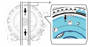
- (1) Set two straight edge rulers along the alignment surfaces of the end cover with the brake housing as shown in the figure.
- (2) Measure the positions (2 locations) shown in the figure using a depth gauge and calculate the average value.
-
A :Straight edge rulers
- (3) Subtract the thickness of the straight edge rulers from the average value.
11. Assemble the thrust needle bearing.
-
Note
-
• Thrust needle bearing size: Inner diameter approx. 18.5 mm {0.728 in}
12. Assemble the reduction sun gear.
13. Assemble the thrust needle bearing.
-
Note
-
• Thrust needle bearing size: Outer diameter approx. 38 mm {1.5 in}
14. Assemble the thrust washer.
-
Note
-
• Thrust washer size: Outer diameter approx. 87.7 mm {3.45 in}
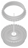
15. Assemble the reduction internal gear to the rear internal gear using the following procedure:
- (1) Assemble the reduction internal gear to the rear internal gear.
-
- (2) Assemble the snap ring.
-
16. Assemble the rear internal gear and reduction internal gear component.
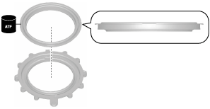
17. Assemble the retaining plate.
-
Note
-
• Retaining plate size: Inner diameter approx. 137.2 mm {5.402 in}
18. Assemble the drive plates and driven plates using the following procedure:
-
Caution
-
• The driven plate has a similar shape to the retaining plate used for the 2-6 brake clearance adjustment. Before assembling the driven plate, always verify the plate thickness and the shape.
-
Note
-
• Drive plate size: Outer diameter approx. 160.4 mm {6.315 in}
• Driven plate size: Inner diameter approx. 137.2 mm {5.402 in}, thickness approx. 1.6 mm {0.063 in}
- (1) Apply ATF (ATF FZ) to the drive plates and driven plates.
-
-
Caution
-
• If the drive plate is replaced with a new one, immerse it in ATF (ATF FZ) for 2 h or more to permeate the facing with ATF.
- (2) Assemble the drive plates and driven plates.
-
-
Assembly order
-
Drive plate—driven plate—drive plate—driven plate—drive plate
A :Drive plate
B :Driven plate
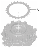
19. Assemble the retaining plate using the following procedure:
- (1) Measure the 2-6 brake clearance and select the appropriate retaining plate. (See 2-6 BRAKE CLEARANCE MEASUREMENT/ADJUSTMENT.)
-
-
Note
-
• If the retaining plate is assembled for the 2-6 brake clearance measurement/adjustment, the following retaining plate assembly procedure is not necessary.
- (2) Assemble the retaining plate selected in Step (1).
-
-
Note
-
• Retaining plate: Inner diameter approx. 137.2 mm {5.402 in}
A :Selection
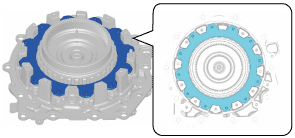
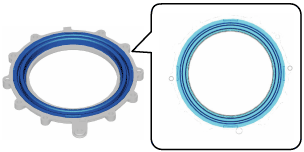
20. Assemble the springs and retainer component.
-
Note
-
• Springs and retainer component size: Inner diameter approx. 150.4 mm {5.921 in}
21. Assemble the 2-6 brake piston to the brake housing using the following procedure:
-
Note
-
• If the 2-6 brake piston is assembled to the brake housing for the 2-6 brake clearance measurement/adjustment, the following assembly of the 2-6 brake piston to the brake housing procedure is not necessary.
- (1) Apply ATF (ATF FZ) to the 2-6 brake piston lip.
- (2) Assemble the 2-6 brake piston.
-
22. Assemble the brake housing using the following procedure:
|
1
|
Brake housing
|
|
2
|
8 Bolts (M6 x 1.0 bolt, length approx. 25 mm {0.98 in})
|
- (1) Assemble the brake housing.
-
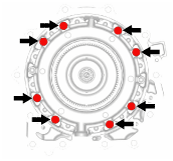
- (2) Assemble and tighten the bolts shown in the figure uniformly.
-
-
Caution
-
• If the bolts are not tightened uniformly, the brake housing will slant and parts could be damaged due to the spring force of the springs and retainer component in the brake housing.
-
Note
-
• Bolt size: M6 x 1.0 bolt (length approx. 25 mm {0.98 in})
-
Tightening torque
-
8—10 N·m {82—101 kgf·cm, 71—88 in·lbf}
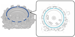
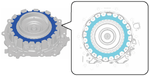
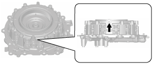
23. Perform an operation verification of the 2-6 brake using the following procedure:
- (1) Blow compressed air into the oil passage shown in the figure and verify the operation condition of the 2-6 brake.
-
-
Warning
-
• Always wear protective eye wear when using the air compressor. Otherwise, ATF or dirt particles blown off by the air compressor could get into the eyes.
-
Note
-
• To prevent damage to parts, always use an air compressor which is adjusted to the indicated pressure.
-
Compressed air pressure
-
0.39—0.44 MPa {4.0—4.4 kgf/cm2, 57—63 psi}
-