 |
am2zzw00014964
CYLINDER HEAD GASKET REPLACEMENT [SKYACTIV-G 1.3, SKYACTIV-G 1.5]
id0110q3800700
1. Disconnect the negative battery cable. (See NEGATIVE BATTERY CABLE DISCONNECTION/CONNECTION.)
2. Remove the plug hole plate. (See PLUG HOLE PLATE REMOVAL/INSTALLATION [SKYACTIV-G 1.3, SKYACTIV-G 1.5].)
3. Remove the following parts. (See IGNITION COIL/ION SENSOR REMOVAL/INSTALLATION [SKYACTIV-G 1.3, SKYACTIV-G 1.5].)
4. Remove the front under cover No.2. (See FRONT UNDER COVER No.2 REMOVAL/INSTALLATION.)
5. Remove the front splash shield (RH). (See SPLASH SHIELD REMOVAL/INSTALLATION.)
6. Remove the drive belt. (See DRIVE BELT REMOVAL/INSTALLATION [SKYACTIV-G 1.3, SKYACTIV-G 1.5].)
7. Drain the engine oil. (See ENGINE OIL REPLACEMENT [SKYACTIV-G 1.3, SKYACTIV-G 1.5].)
8. Drain the engine coolant. (See ENGINE COOLANT REPLACEMENT [SKYACTIV-G 1.3, SKYACTIV-G 1.5].)
9. Remove the intake manifold. (See INTAKE-AIR SYSTEM REMOVAL/INSTALLATION [SKYACTIV-G 1.3, SKYACTIV-G 1.5].)
10. Set aside the exhaust manifold to the vehicle rear. (See EXHAUST SYSTEM REMOVAL/INSTALLATION [SKYACTIV-G 1.3, SKYACTIV-G 1.5].)
11. Remove the vacuum pump. (See VACUUM PUMP REMOVAL/INSTALLATION [SKYACTIV-G 1.3, SKYACTIV-G 1.5].)
12. Remove the high pressure fuel pump and rear housing. (See HIGH PRESSURE FUEL PUMP REMOVAL/INSTALLATION [SKYACTIV-G 1.3, SKYACTIV-G 1.5].)
13. Disconnect 2 heater hoses from the following parts.
14. Disconnect the water hose No.1 from the flange. (With coolant control valve, ATX) (See OIL COOLER REMOVAL/INSTALLATION [CW6A-EL].)
15. Disconnect the water hose No.2 from the coolant control valve. (With coolant control valve, ATX) (See OIL COOLER REMOVAL/INSTALLATION [CW6A-EL].)
16. Removal the coolant control valve. (With coolant control valve) (See COOLANT CONTROL VALVE REMOVAL/INSTALLATION [SKYACTIV-G 1.3, SKYACTIV-G 1.5].)
17. Disconnect the radiator hose (upper and lower). (Without coolant control valve)
18. Remove the oil pan. (See OIL PAN REMOVAL/INSTALLATION [SKYACTIV-G 1.3, SKYACTIV-G 1.5].)
19. Remove the timing chain and chain guide. (See TIMING CHAIN REMOVAL/INSTALLATION [SKYACTIV-G 1.3, SKYACTIV-G 1.5].)
20. Remove the OCV. (See OIL CONTROL VALVE (OCV) REMOVAL/INSTALLATION [SKYACTIV-G 1.3, SKYACTIV-G 1.5].)
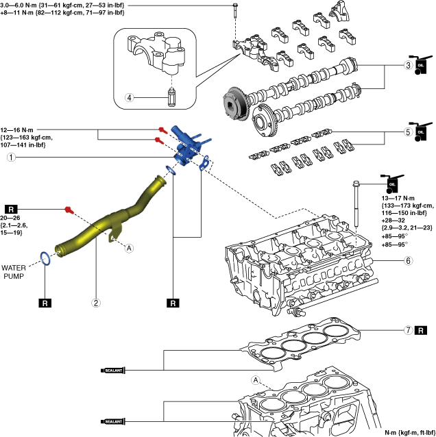
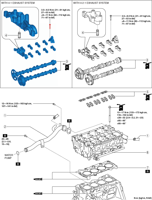
21. Remove in the order indicated in the table.
22. Install in the reverse order of removal.
23. Refill with the specified type and amount of the engine oil. (See ENGINE OIL REPLACEMENT [SKYACTIV-G 1.3, SKYACTIV-G 1.5].)
24. Refill the engine coolant. (See ENGINE COOLANT REPLACEMENT [SKYACTIV-G 1.3, SKYACTIV-G 1.5].)
25. Start the engine, and inspect and adjust the following:
Without coolant control valve
am2zzw00014964
|
|
1
|
Water hose (ATX)
|
|
2
|
Water inlet pipe
|
|
3
|
Camshaft
(See Camshaft Removal Note.)
(See Camshaft Installation Note.)
|
|
4
|
OCV oil filter
|
|
5
|
Rocker arm
(See Rocker Arm Removal Note.)
(See Rocker Arm Installation Note.)
|
|
6
|
Cylinder head
(See Cylinder Head Removal Note.)
|
|
7
|
Cylinder head gasket
|
With coolant control valve
am2zzw00014965
|
|
1
|
Flange
|
|
2
|
Water inlet pipe
|
|
3
|
Camshaft
(See Camshaft Removal Note.)
(See Camshaft Installation Note.)
|
|
4
|
OCV oil filter
|
|
5
|
Rocker arm
(See Rocker Arm Removal Note.)
(See Rocker Arm Installation Note.)
|
|
6
|
Cylinder head
(See Cylinder Head Removal Note.)
|
|
7
|
Cylinder head gasket
|
Camshaft Removal Note
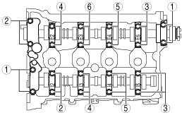
1. Loosen the camshaft cap installation bolts in a few passes in the order shown in the figure and remove the camshaft caps.
Without coolant control valve (4-1 exhaust system)
adejjw00011442
|
Without coolant control valve (4-2-1 exhaust system), With coolant control valve
am6zzw00011874
|
2. Remove the camshaft.
Rocker Arm Removal Note
1. Keep the rocker arms in the order of removal to enable reassembly in their original positions.
Cylinder Head Removal Note
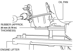
1. Temporarily install the oil pan to support the engine from under the vehicle.
2. Support the engine (oil pan) using a commercially available engine lifter or garage jack.
am2zzw00012644
|
3. Remove the chain of the SST suspending the engine and set it in a place which does not interfere with the servicing.
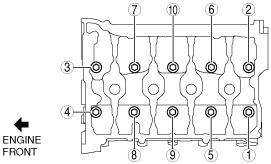
4. Loosen the cylinder head installation bolts in two or three passes in the order shown in the figure and remove them.
am3uuw00008817
|
5. Remove the cylinder head.
Cylinder Head Installation Note
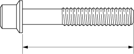
1. Measure the length of the cylinder head bolt.
amxzzw00003984
|
2. When a cylinder head bolt is reused, apply engine oil to any part of the following:
3. Completely remove any oil, dirt, and silicone sealant adhering to the cylinder block.
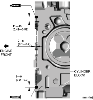
4. Apply silicone sealant (TB1217D or equivalent) to the areas shown in the figure.
am3zzw00019915
|
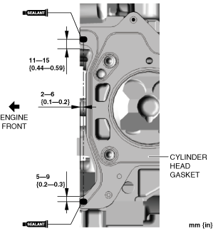
5. Install a new cylinder head gasket to the cylinder block.
6. Apply silicone sealant (TB1217D or equivalent) to the areas shown in the figure.
am3zzw00019918
|
7. Set the cylinder head on the cylinder block.
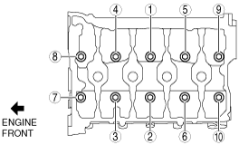
8. Tighten the cylinder head bolts in the order shown in the following 4 steps.
am3uuw00008818
|
9. Install the SST chain which was set aside, and secure the engine.
10. Remove the engine lifter or garage jack.
11. Remove the temporarily assembled oil pan.
Rocker Arm Installation Note
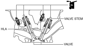
1. Apply engine oil to the HLAs and the end of the valve stems.
am3uuw00008819
|
2. Install the rocker arms to the same positions as before removal.
Camshaft Installation Note
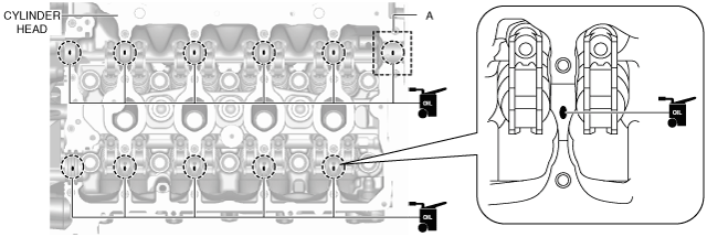
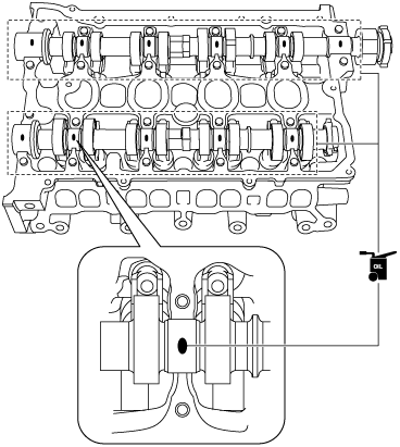
1. Apply SAE 90 gear oil or equivalent, or engine oil to the positions shown in the figure.
am2zzw00011105
|
2. Apply gear oil (SAE 90 or equivalent) or engine oil to the thrust surface (both surfaces front and back) of the front journal on each camshaft.
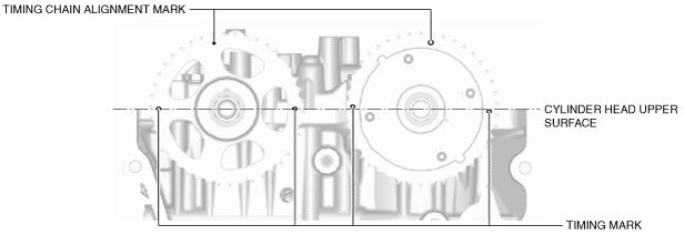
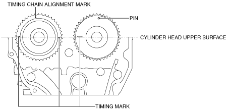
3. Install the camshaft with the cylinder No.1 cam aligned around the top dead center (TDC) position.
Without coolant control valve (4-1 exhaust system)
am2zzw00012647
|
Without coolant control valve (4-2-1 exhaust system), With coolant control valve
am2zzw00012648
|
4. Apply SAE 90 gear oil or equivalent, or engine oil to the central area of each journal on the camshaft.
am6zzw00011876
|
5. Apply SAE 90 gear oil or equivalent, or engine oil to the thrust surface of the front camshaft cap.
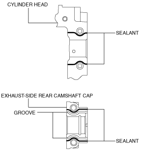
6. Apply sealant (LOCTITE 962T or equivalent) to the rear camshaft cap installation area on the exhaust side of the cylinder head or the rear camshaft cap on the exhaust side.
am2zzw00012649
|
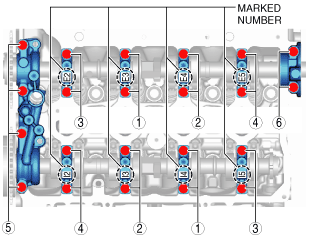
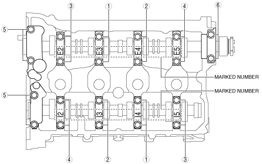
7. Install the camshaft caps in the order of the marked numbers, and temporarily tighten the camshaft cap installation bolts evenly in 2—3 rounds.
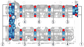
8. Tighten the camshaft cap installation bolts in two steps in the order shown in the figure.
Without coolant control valve (4-1 exhaust system)
am2zzw00012650
|
Without coolant control valve (4-2-1 exhaust system), With coolant control valve
am3uuw00008824
|
Water Inlet Pipe Installation Note (Without Coolant Control Valve)
1. Clean away the sealant adhering to the bolt hole on the cylinder block side of the water inlet pipe stay.
2. Apply engine coolant to the O-ring.
3. Install the O-ring to the water inlet pipe.
4. Insert the water inlet pipe into the water pump being careful not to damage the O-ring.
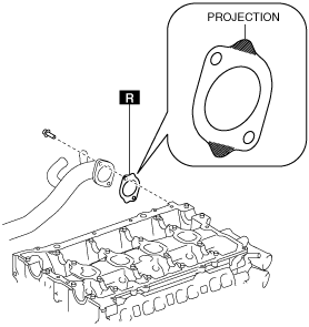
5. Install the water inlet pipe gasket with the gasket projection facing the direction shown in the figure.
ac5uuw00000500
|
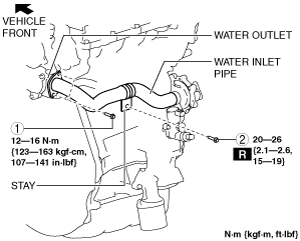
6. Tighten the bolts in the order shown in the figure.
am2zzw00012651
|
Water Inlet Pipe and Flange Installation Note (With Coolant Control Valve)
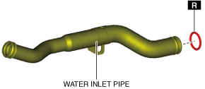
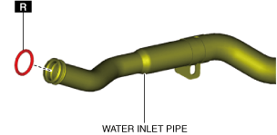
1. Apply engine coolant to a new O-ring (water pump side).
2. Install the O-ring to the water inlet pipe.
ac5wzw00011571
|
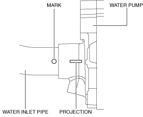
3. Insert the water inlet pipe into the water pump so that the marked position is aligned with the projection position.
ac5wzw00011077
|
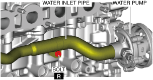
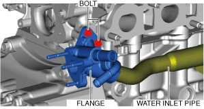
4. Temporarily tighten the bolt shown in the figure.
am2zzw00014967
|
5. Apply engine coolant to a new O-ring (flange side).
6. Install the O-ring to the water inlet pipe.
ac5wzw00011573
|
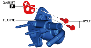
7. Assemble the flange, gasket and bolts.
ac5wzw00011574
|
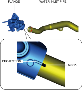
8. Assemble the water inlet pipe and the flange so that the marked position is aligned with the projection position.
ac5wzw00011340
|
9. Temporarily tighten the bolt shown in the figure.
ac5wzw00011575
|
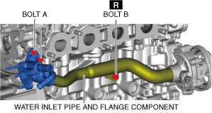
10. Tighten the bolts shown in the figure.
am2zzw00014968
|