 |
am2zzw00007810
REAR WINDOW DEFOGGER SYSTEM INSPECTION
id091200020400
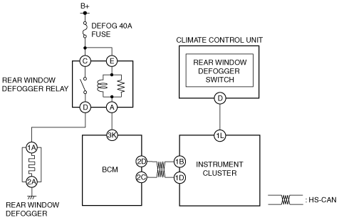
Full-auto Air Conditioner
System wiring diagram
am2zzw00007810
|
Inspection Procedure
|
Step |
Inspection |
Action |
|
|---|---|---|---|
|
1
|
VERIFY INSTRUMENT CLUSTER DTCs
• Switch the ignition ON (engine off or on).
• Perform the DTC inspection for the instrument cluster using the M-MDS.
• Is a DTC displayed?
|
Yes
|
Repair the malfunctioning location according to the applicable DTC troubleshooting.
|
|
No
|
Go to the next step.
|
||
|
2
|
DETERMINE MALFUNCTIONING LOCATION BY PERFORMING PID/DATA MONITOR INSPECTION
• Display the BCM PID [R_DEF_RLY] using the M-MDS.
• Turn the rear window defogger switch on.
• Is the PID value on?
|
Yes
|
Go to Step 5.
|
|
No
|
Go to the next step.
|
||
|
3
|
INSPECT REAR WINDOW DEFOGGER SWITCH CONDITION BY PERFORMING PID/DATA MONITOR INSPECTION
• Display the climate control unit PID [R/DEF_SW] using the M-MDS.
• Turn the rear window defogger switch on.
• Is the PID value on?
|
Yes
|
Go to the next step.
|
|
No
|
Replace the climate control unit, then go to Step 10.
|
||
|
4
|
INSPECT REAR WINDOW DEFOGGER OPERATION REQUEST SIGNAL FROM CLIMATE CONTROL UNIT BY PERFORMING PID/DATA MONITOR INSPECTION
• Display the climate control unit PID [R/DEF_CS] using the M-MDS.
• Turn the rear window defogger switch on.
• Is the PID value on?
|
Yes
|
Replace the BCM, then go to Step 10.
|
|
No
|
Replace the climate control unit, then go to Step 10.
|
||
|
5
|
INSPECT REAR WINDOW DEFOGGER RELAY
• Switch the ignition OFF (LOCK).
• Disconnect the negative battery cable.
• Remove the rear window defogger relay.
(See RELAY LOCATION.)
• Inspect the rear window defogger relay.
(See RELAY INSPECTION.)
• Is the rear window defogger relay normal?
|
Yes
|
Go to the next step.
|
|
No
|
Replace the rear window defogger relay, then go to Step 10.
(See RELAY LOCATION.)
|
||
|
6
|
INSPECT REAR WINDOW DEFOGGER RELAY CIRCUIT FOR SHORT TO GROUND OR OPEN CIRCUIT
• Verify that the rear window defogger relay is removed.
• Connect the negative battery cable.
• Measure the voltage at rear window defogger relay terminals C and E (vehicle wiring harness side).
• Is the voltage B+?
|
Yes
|
Go to the next step.
|
|
No
|
Inspect the DEFOG 40 A fuse.
• If the fuse is blown:
• If the fuse is damaged:
• If the fuse is normal:
Go to Step 10.
|
||
|
7
|
INSPECT REAR WINDOW DEFOGGER CIRCUIT FOR SHORT TO GROUND OR OPEN CIRCUIT
• Install the rear window defogger relay.
• Turn the rear window defogger switch on.
• Measure the voltage at rear window defogger terminal 1A (vehicle wiring harness side).
• Is the voltage B+?
|
Yes
|
Go to the next step.
|
|
No
|
Refer to the wiring diagram and verify if there is a common connector between rear window defogger relay terminals D and rear window defogger terminal 1A.
If there is a common connector:
• Inspect the common connector and terminals for corrosion, damage, or disconnection and the common wiring harnesses for short to ground or open circuit to determine the malfunctioning location.
• Repair or replace the malfunctioning location.
If there is no common connector:
• Repair or replace the wiring harness which is shorted to ground or has an open circuit.
After repair procedure, go to Step 10.
|
||
|
8
|
INSPECT REAR WINDOW DEFOGGER
• Inspect the rear window defogger.
• Is the rear window defogger normal?
|
Yes
|
Go to the next step.
|
|
No
|
Repair the rear window defogger, then go to Step 10.
(See REAR WINDOW DEFOGGER REPAIR.)
|
||
|
9
|
INSPECT BCM CIRCUIT FOR SHORT TO GROUND OR OPEN CIRCUIT
• Switch the ignition ON (engine off or on).
• Measure the voltage at BCM terminal 3K (vehicle wiring harness side).
• Is the voltage B+?
|
Yes
|
Replace the BCM, then go to the next step.
|
|
No
|
Refer to the wiring diagram and verify if there is a common connector between BCM terminal 3K and rear window defogger relay terminal A.
If there is a common connector:
• Inspect the common connector and terminals for corrosion, damage, or disconnection and the common wiring harnesses for short to ground or open circuit to determine the malfunctioning location.
• Repair or replace the malfunctioning location.
If there is no common connector:
• Repair or replace the wiring harness which is shorted to ground or has an open circuit.
After repair, go to the next step.
|
||
|
10
|
VERIFY IF MALFUNCTION IS RESOLVED
• Does the rear window defogger system operate normally?
|
Yes
|
Explain the contents of the servicing to the customer.
|
|
No
|
If the malfunction has not been resolved, repeat the inspection from Step 1.
|
||
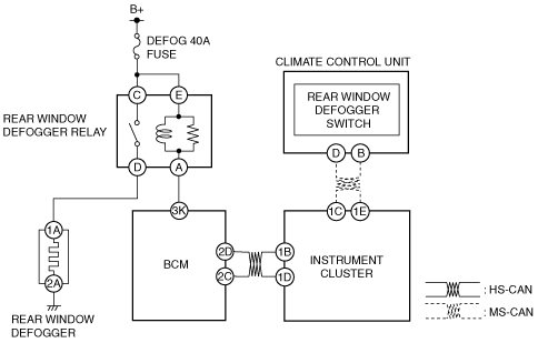
Manual Air Conditioner
System wiring diagram
am2zzw00007811
|
Inspection Procedure
|
Step |
Inspection |
Action |
|
|---|---|---|---|
|
1
|
VERIFY INSTRUMENT CLUSTER DTCs
• Switch the ignition ON (engine off or on).
• Perform the DTC inspection for the instrument cluster using the M-MDS.
• Is a DTC displayed?
|
Yes
|
Repair the malfunctioning location according to the applicable DTC troubleshooting.
|
|
No
|
Go to the next step.
|
||
|
2
|
DETERMINE MALFUNCTIONING LOCATION BY PERFORMING PID/DATA MONITOR INSPECTION
• Display the BCM PID [R_DEF_RLY] using the M-MDS.
• Turn the rear window defogger switch on.
• Is the PID value on?
|
Yes
|
Go to Step 7.
|
|
No
|
Go to the next step.
|
||
|
3
|
INSPECT REAR WINDOW DEFOGGER SWITCH CONDITION BY INSPECTING CLIMATE CONTROL UNIT
• Perform terminal voltage inspection at climate control unit terminal D.
• Is the voltage normal?
|
Yes
|
Go to the next step.
|
|
No
|
Replace the climate control unit, then go to Step 12.
|
||
|
4
|
INSPECT CLIMATE CONTROL UNIT CIRCUIT FOR SHORT TO GROUND
• Disconnect the instrument cluster connector.
• Verify that the climate control unit connector is disconnected.
• Inspect for continuity between climate control unit terminal D (vehicle wiring harness side) and body ground.
• Is there continuity?
|
Yes
|
Refer to the wiring diagram and verify if there is a common connector between climate control unit terminal D and instrument cluster terminal 1L.
If there is a common connector:
• Inspect the common connector and terminals for corrosion, damage, or disconnection and the common wiring harnesses for short to ground to determine the malfunctioning location.
• Repair or replace the malfunctioning location.
If there is no common connector:
• Repair or replace the wiring harness which is shorted to ground.
After repair procedure, go to Step 12.
|
|
No
|
Go to the next step.
|
||
|
5
|
INSPECT CLIMATE CONTROL UNIT CIRCUIT FOR OPEN CIRCUIT
• Verify that the climate control unit connector and the instrument cluster connector are disconnected.
• Inspect for continuity between climate control unit terminal D (wiring harness side) and instrument cluster terminal 1L (wiring harness side).
• Is there continuity?
|
Yes
|
Go to the next step.
|
|
No
|
Refer to the wiring diagram and verify if there is a common connector between climate control unit terminal D and instrument cluster terminal 1L.
If there is a common connector:
• Inspect the common connector and terminals for corrosion, damage, or disconnection and the common wiring harnesses for an open circuit to determine the malfunctioning location.
• Repair or replace the malfunctioning location.
If there is no common connector:
• Repair or replace the wiring harness which has an open circuit.
After repair procedure, go to Step 12.
|
||
|
6
|
INSPECT CLIMATE CONTROL UNIT CIRCUIT FOR SHORT TO POWER SUPPLY
• Verify that the climate control unit connector and the instrument cluster connector are disconnected.
• Connect the negative battery cable.
• Switch the ignition ON (engine off or on).
• Turn the rear window defogger switch on.
• Measure the voltage at climate control unit terminal D (vehicle wiring harness side).
• Is the voltage less than 1.0 V?
|
Yes
|
Replace the climate control unit, then go to Step 12.
|
|
No
|
Refer to the wiring diagram and verify if there is a common connector between climate control unit terminal D and instrument cluster terminal 1L.
If there is a common connector:
• Inspect the common connector and terminals for corrosion, damage, or disconnection and the common wiring harnesses for short to power supply to determine the malfunctioning location.
• Repair or replace the malfunctioning location.
If there is no common connector:
• Repair or replace the wiring harness which is shorted to the power supply.
After repair procedure, go to Step 12.
|
||
|
7
|
INSPECT REAR WINDOW DEFOGGER RELAY
• Switch the ignition OFF (LOCK).
• Disconnect the negative battery cable.
• Remove the rear window defogger relay.
(See RELAY LOCATION.)
• Inspect the rear window defogger relay.
(See RELAY INSPECTION.)
• Is the rear window defogger relay normal?
|
Yes
|
Go to the next step.
|
|
No
|
Replace the rear window defogger relay, then go to Step 12.
(See RELAY LOCATION.)
|
||
|
8
|
INSPECT REAR WINDOW DEFOGGER RELAY CIRCUIT FOR SHORT TO GROUND OR OPEN CIRCUIT
• Verify that the rear window defogger relay is removed.
• Connect the negative battery cable.
• Measure the voltage at rear window defogger relay terminals C and E (vehicle wiring harness side).
• Is the voltage B+?
|
Yes
|
Go to the next step.
|
|
No
|
Inspect the DEFOG 40 A fuse.
• If the fuse is blown:
• If the fuse is damaged:
• If the fuse is normal:
Go to Step 12.
|
||
|
9
|
INSPECT REAR WINDOW DEFOGGER CIRCUIT FOR SHORT TO GROUND OR OPEN CIRCUIT
• Install the rear window defogger relay.
• Turn the rear window defogger switch on.
• Measure the voltage at rear window defogger terminal 1A (vehicle wiring harness side).
• Is the voltage B+?
|
Yes
|
Go to the next step.
|
|
No
|
Refer to the wiring diagram and verify if there is a common connector between rear window defogger relay terminals D and rear window defogger terminal 1A.
If there is a common connector:
• Inspect the common connector and terminals for corrosion, damage, or disconnection and the common wiring harnesses for short to ground or open circuit to determine the malfunctioning location.
• Repair or replace the malfunctioning location.
If there is no common connector:
• Repair or replace the wiring harness which is shorted to ground or has an open circuit.
After repair procedure, go to Step 12.
|
||
|
10
|
INSPECT REAR WINDOW DEFOGGER
• Inspect the rear window defogger.
• Is the rear window defogger normal?
|
Yes
|
Go to the next step.
|
|
No
|
Repair the rear window defogger, then go to Step 12.
(See REAR WINDOW DEFOGGER REPAIR.)
|
||
|
11
|
INSPECT BCM CIRCUIT FOR SHORT TO GROUND OR OPEN CIRCUIT
• Switch the ignition ON (engine off or on).
• Measure the voltage at BCM terminal 3K (vehicle wiring harness side).
• Is the voltage B+?
|
Yes
|
Replace the BCM, then go to the next step.
|
|
No
|
Refer to the wiring diagram and verify if there is a common connector between BCM terminal 3K and rear window defogger relay terminal A.
If there is a common connector:
• Inspect the common connector and terminals for corrosion, damage, or disconnection and the common wiring harnesses for short to ground or open circuit to determine the malfunctioning location.
• Repair or replace the malfunctioning location.
If there is no common connector:
• Repair or replace the wiring harness which is shorted to ground or has an open circuit.
After repair, go to the next step.
|
||
|
12
|
VERIFY IF MALFUNCTION IS RESOLVED
• Does the rear window defogger system operate normally?
|
Yes
|
Explain the contents of the servicing to the customer.
|
|
No
|
If the malfunction has not been resolved, repeat the inspection from Step 1.
|
||