1. Remove the ABS wheel-speed sensor. (See FRONT ABS WHEEL-SPEED SENSOR REMOVAL/INSTALLATION.)
2. Drain the transaxle oil. (See TRANSAXLE OIL REPLACEMENT [F35M-R].) (See AUTOMATIC TRANSAXLE FLUID (ATF) REPLACEMENT [FN4A-EL].)
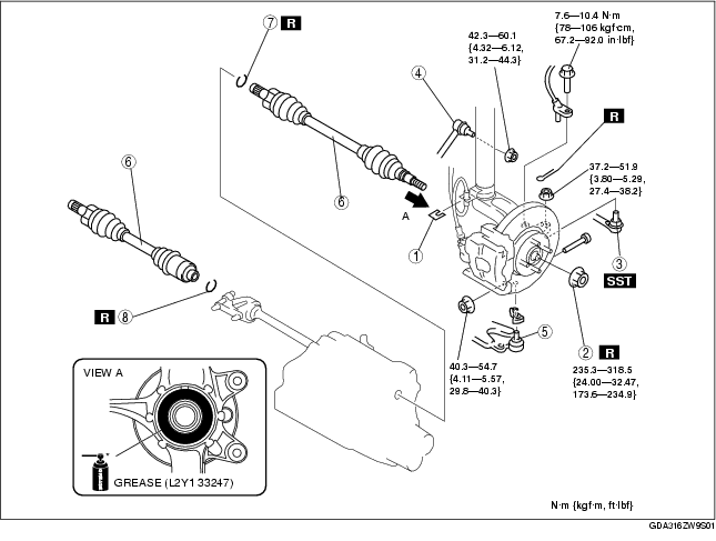
3. Remove in the order indicated in the table.
4. Install in the reverse order of removal.
|
1
|
Clip
|
|
2
|
Locknut
|
|
3
|
Tie-rod end
(See Tie-rod End Removal Note)
|
|
4
|
Stabilizer control link (upper side)
|
|
5
|
Front lower arm ball joint
|
|
6
|
Drive shaft
(See Drive Shaft Removal Note)
|
|
7
|
Clip (drive shaft (LH))
|
|
8
|
Clip (joint shaft)
(See Clip Installation Note)
|
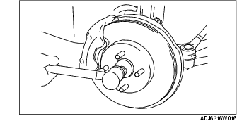
1. Install a spare nut onto the drive shaft.
2. Tap the nut with copper hammer and separate the drive shaft from the wheel hub.
3. Remove the drive shaft from the wheel hub.
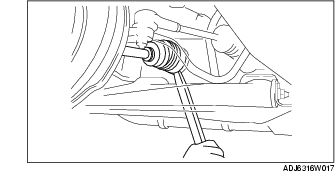
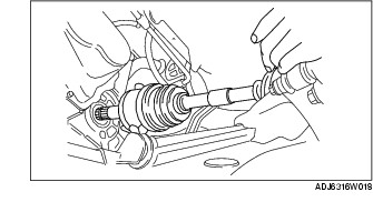
4. Separate the drive shaft (LH) from the transaxle by prying with a bar inserted between the outer ring and the transaxle.
5. Disconnect the drive shaft (RH) from the joint shaft by tapping the transaxle side outer ring lightly with a brass bar and hammer.
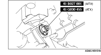
6. Install the SST to the transaxle after the drive shaft is removed.
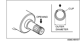
1. Install a new clip onto the drive shaft with the opening facing upward.
2. After installation, measure the outer diameter.
Outer diameter
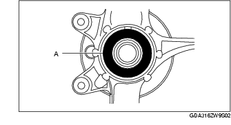
1. Apply grease (L2Y1 33247) to the wheel bearing inner race and drive shaft contact surface (Area A in figure).
2. Insert the drive shaft to the wheel hub.
3. Apply transaxle oil to the oil seal lip.
4. Install the drive shaft to the transaxle.
5. After installation, pull the transaxle side outer ring forward to confirm that the drive shaft is securely held by the clip.
1. Apply grease (L2Y1 33247) to the wheel bearing inner race and drive shaft contact surface (Area A in figure).
2. Insert the drive shaft to the wheel hub.
3. Insert the drive shaft to the joint shaft.
4. After installation, pull the transaxle side outer ring forward to confirm that the drive shaft is securely held by the clip.