1. Remove the accelerator pedal. (See ACCELERATOR PEDAL REMOVAL/INSTALLATION [ZY].)
2. Remove the steering shaft lower bolts and detach the steering shaft form the steering gear.STEERING WHEEL AND COLUMN REMOVAL/INSTALLATION.)
3. Remove the clutch master cylinder. (See CLUTCH MASTER CYLINDER REMOVAL/INSTALLATION.)
4. Remove in the order indicated in the table.
5. Install in the reverse order of removal.
.
|
1
|
Brake switch connector
|
|
2
|
Clutch switch connector
|
|
3
|
Brake switch
|
|
4
|
Clutch switch
|
|
5
|
Joint pin
(See Joint pin removal note)
|
|
6
|
Pedal component
|
|
7
|
Pedal pad
|
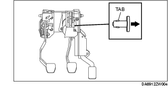
1. Loosen the pedal component installation nut.
2. Remove the joint pin while pressing the tab of the joint pin.
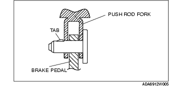
1. Install the new joint pin by aligning the pin holes of brake pedal and push rod fork, before installing the pedal component completely.
2. Make sure that the joint pin tab is caught correctly.
3. Tighten the pedal component installation nuts.
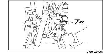
1. Install the new brake switch to the brake pedal, and secure it by turning it counterclockwise 45°.
1. Inspect the brake pedal. (See BRAKE PEDAL INSPECTION.)
2. With the brake pedal in its original position, install the brake switch to the brake switch connector.
1. Remove the accelerator pedal. (See ACCELERATOR PEDAL REMOVAL/INSTALLATION [ZY].)
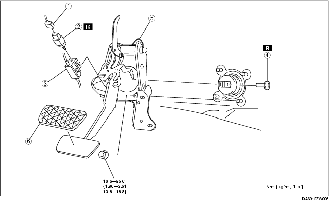
2. Remove in the order indicated in the table.
3. Install in the reverse order of removal.
.
|
1
|
Brake switch connector
|
|
2
|
Brake switch
|
|
3
|
Interlock unit
(See Interlock unit removal note.)
|
|
4
|
Joint pin
(See Joint pin removal note.)
(See Joint pin installation note.)
|
|
6
|
Brake Pedal
|
|
7
|
Pedal pad
|
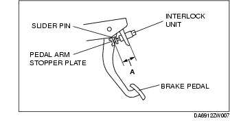
1. Before removing the interlock unit, measure length A (between interlock unit and pedal arm stopper plate) and write down the measurement for reference when installing.
1. Verify that length A measured prior to removing the interlock unit has not changed, and then install the interlock unit.
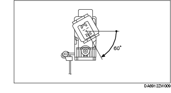
1. Install the new brake switch to the interlock unit, and secure it by turning it clockwise 60°.
1. Inspect the brake pedal. (See BRAKE PEDAL INSPECTION.)
2. With the brake pedal in its original position, install the brake switch to the brake switch connector.