1. Disconnect the negative battery cable.
2. Remove the battery, battery tray and battery tray bracket.
3. Remove the air cleaner cover. (See INTAKE-AIR SYSTEM REMOVAL/INSTALLATION [ZY].)
4. Remove the front tires and splash shield.
5. Remove the EGR pipe and hose. (See INTAKE-AIR SYSTEM REMOVAL/INSTALLATION [ZY].)
6. Drain the ATF. (See AUTOMATIC TRANSAXLE FLUID (ATF) REPLACEMENT [FN4A-EL].)
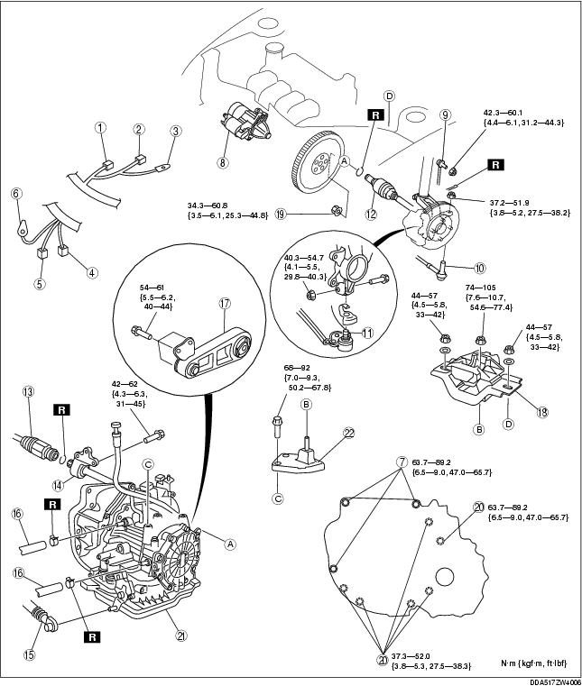
7. Remove in the order shown in the figure.
8. Install in the reverse order of removal.
9. Add ATF to the specified level. (See AUTOMATIC TRANSAXLE FLUID (ATF) REPLACEMENT [FN4A-EL].)
10. Carry out the mechanical system test. (See MECHANICAL SYSTEM TEST [FN4A-EL].)
|
Service item
|
Test item
|
||
|---|---|---|---|
|
Line pressure test
|
Stall test
|
Time lag test
|
|
|
ATX replacement
|
X
|
|
|
|
ATX overhaul
|
X
|
X
|
X
|
|
Torque converter replacement
|
X
|
X
|
|
|
Oil pump replacement
|
X
|
|
|
|
Clutch system replacement
|
X
|
|
X
|
11. Carry out the road test. (See ROAD TEST [FN4A-EL].)
.
|
1
|
Input/turbine speed sensor connector
|
|
2
|
VSS connector
|
|
3
|
GND wiring harness
|
|
4
|
Transaxle connector
|
|
5
|
TR switch connector
|
|
6
|
GND wiring harness
|
|
7
|
Transaxle mounting bolt (upper side)
|
|
8
|
Starter
|
|
9
|
Stabilizer control link
|
|
10
|
Tie-rod end ball joint
(See Tie-rod End Removal Note.)
|
|
11
|
Lower arm ball joint
|
|
12
|
Drive shaft
|
|
13
|
Drive shaft
|
|
14
|
Joint shaft
|
|
15
|
Selector cable
|
|
16
|
Oil hose
|
|
17
|
No.1 engine mount
|
|
18
|
No.4 engine mount rubber
|
|
19
|
Torque converter installation nuts
|
|
20
|
Transaxle mounting bolt (lower side)
|
|
21
|
Transaxle
(See Transaxle Removal Note.)
(See Transaxle Installation Note.)
|
|
22
|
No.4 engine bracket
|
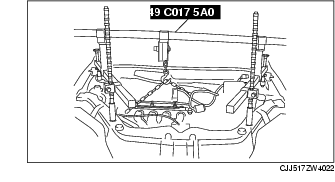
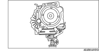
1. Remove the dipstick of engine.
2. Using the bolts part number 99794 1025 or M10× 1.25, length 25 mm {0.98 in} to install the SST to the position as shown in the figure.
Tightening torque
3. Install the SST using the following procedure.
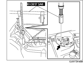

4. Support the engine using the SST.
5. Remove the battery tray bracket, No.4 engine mount rubber and bracket.
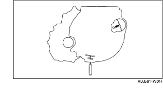
1. Using the flathead screwdriver, lock the drive plate.
2. Remove the torque converter nuts from the starter installation hole.
1. Adjust the SST and lean the engine toward the transaxle.
2. Support the transaxle on a jack.
3. Remove the transaxle mounting bolts.
4. Remove the transaxle.
1. Set the transaxle on a jack and lift it.
2. Install the transaxle mounting bolts.
Tightening torque
1. Using the flathead screwdriver, lock the drive plate.
2. Tighten the torque converter mounting nuts.
Tightening torque
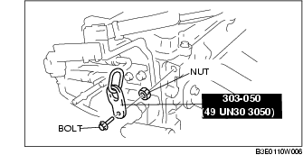
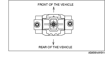
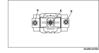
1. Verify that the No.4 engine mount rubber is installed as shown.
2. Adjust the SST (engine support), and align the hole of the No.4 engine mount rubber with the stud bolt of transaxle.
3. Set the transaxle on a garage jack and lift it.
4. Tighten nuts A, B in the order of A to B.
Tightening torque
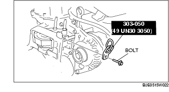
1. Adjust the SST (engine support), and align the hole of the No.1 engine mount with the bolt hole of transaxle.
2. Tighten bolt.
Tightening torque