Diagnostic procedure
|
STEP
|
INSPECTION
|
ACTION
|
|
|---|---|---|---|
|
1
|
INSPECT WHETHER MALFUNCTION IS CAUSED BY POOR CONNECTION OF EPS CM OR PIN DEFORMATION
• Turn the ignition switch off.
• Inspect connection of the EPS CM and wiring harness.
• Disconnect the EPS CM connector.
• Inspect whether malfunction is caused by bent or poorly connected EPS CM connector pin.
• Are the connector connection, connector pins, and wiring harness normal?
|
Yes
|
Go to the next step.
|
|
No
|
Repair or replace the faulty connector wiring harness, then go to Step 5.
|
||
|
2
|
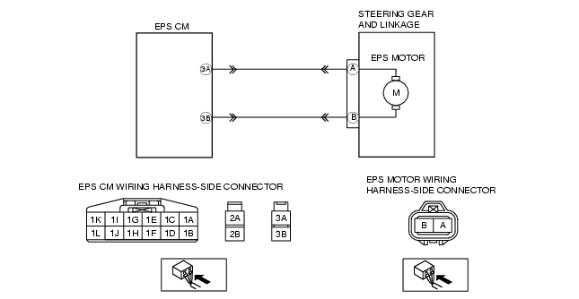
INSPECT EPS MOTOR CIRCUIT FOR OPEN CIRCUIT
• Disconnect the noise filter connector.
• Inspect for continuity between the EPS CM terminals and noise filter terminals.
• Is there continuity?
|
Yes
|
Go to the next step.
|
|
No
|
Repair or replace the wiring harness for open circuit between the EPS CM and EPS motor, then go to Step 5.
|
||
|
3
|
INSPECT EPS MOTOR CIRCUIT FOR SHORT TO POWER
• Measure the voltage between the EPS motor terminals and ground.
• Is there any B+?
|
Yes
|
Repair or replace the wiring harness for short to power between the EPS CM and EPS motor, then go to Step 5.
|
|
No
|
Go to the next step.
|
||
|
4
|
INSPECT EPS MOTOR CIRCUIT FOR SHORT TO GROUND
• Inspect for continuity between the EPS motor terminals and ground.
• Is there continuity?
|
Yes
|
Repair or replace the wiring harness for short to ground between the EPS CM and EPS motor, then go to the next step.
|
|
No
|
Replace the steering gear and linkage (EPS motor), then go to the next step.
|
||
|
5
|
VERIFY TROUBLESHOOTING COMPLETED
• Make sure to reconnect all disconnected connectors.
• Clear the DTC from the memory.
(See Clearing DTCs Procedure.)
• Turn the ignition switch off.
• Start the engine.
• Is the same DTC present?
|
Yes
|
Replace the EPS CM, then go to the next step.
|
|
No
|
Go to the next step.
|
||
|
6
|
VERIFY AFTER REPAIR PROCEDURE
• Are any other DTCs present?
|
Yes
|
Go to the applicable DTC inspection.
(See DTC Table.)
|
|
No
|
DTC troubleshooting completed.
|
||