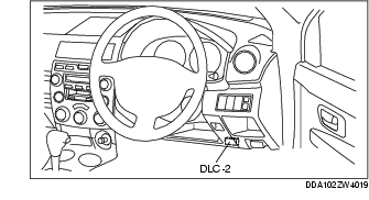
1. Connect the WDS or equivalent to the vehicle DLC-2 connector.
2. Retrieve DTCs using the WDS or equivalent.
1. After repairs have been made, perform the Reading DTCs Procedure.
2. Clear DTCs using the WDS or equivalent.
3. Verify that the customer's concern has been resolved.
1. Connect the WDS or equivalent to the vehicle DLC-2 connector.
2. Access and monitor PIDs using the WDS or equivalent.
|
DTC
|
Diagnosis system component
|
Page
|
|---|---|---|
|
WDS or equivalent
|
||
|
B1317
|
Battery power supply
|
(See DTC B1317, B1318.)
|
|
B1318
|
Battery power supply
|
|
|
B1342
|
EPS CM (internal malfunction)
|
(See DTC B1342, B2143.)
|
|
B2143
|
EPS CM (memory malfunction)
|
|
|
B2278
|
Torque sensor
|
(See DTC B2278.)
|
|
B2477
|
EPS CM configuration
|
(See DTC B2477.)
|
|
C1099
|
EPS motor
|
(See DTC C1099.)
|
|
U0073
|
CAN bus communication error
|
|
|
U0100
|
CAN bus communication error
|
|
|
U2023
|
CAN communication error
|
|
PID Name
(Definition)
|
Unit/
Condition
|
Condition/Specification
|
Action
|
EPS CM terminal
|
|---|---|---|---|---|
|
CCNT
(Number of continuous codes)
|
-
|
• DTCs are detected: 1-255
• No DTCs are detected: 0
|
Perform inspection using appropriate DTC.
|
-
|
|
EPS_MTR
(EPS motor drive signal)
|
A
|
• Steering wheel is not turned: Near 0 A
• Steering wheel is turned right: 0-127 A (varying within the range)
• Steering wheel is turned left: 0- -128 A (varying within the range)
|
Inspect EPS CM. (See EPS CONTROL MODULE INSPECTION.)
Inspect EPS motor circuit.
Inspect power supply circuit (such as IG switch, fuse).
|
3A, 3B
|
|
RPM
(Engine speed signal)
|
RPM
|
• Engine speed 1,000 rpm: 1000RPM
|
Inspect PCM. (See PCM INSPECTION [ZY].)
|
-
|
|
TRQ_SENS
(Torque sensor signal)
|
Nm
|
• Steering wheel is not turned: Near 0 Nm
• Steering wheel is turned right: 0-31.75 Nm (varying within the range)
• Steering wheel is turned left: 0- -32 Nm (varying within the range)
|
Inspect torque sensor circuit.
|
1B
|
|
TRQ_SENS_2
(Torque sensor signal)
|
Nm
|
• Steering wheel is not turned: Near 0 Nm
• Steering wheel is turned right: 0-31.75 Nm (varying within the range)
• Steering wheel is turned left: 0- -32 Nm (varying within the range)
|
Inspect torque sensor circuit.
|
1D
|
|
VPWR
(System battery voltage value)
|
V
|
• Ignition switch at ON: B+
|
Inspect battery.
Inspect power supply circuit (such as IG switch, fuse).
|
1A
|
|
VSS
(Vehicle speed signal)
|
KPH/MPH
|
• Vehicle is stopped:
0 KPH/0 MPH
• Vehicle speed 20 km/h {12 mph}: 20 KPH/12 MPH
|
Inspect PCM. (See PCM INSPECTION [ZY].)
Inspect ABS HU/CM. (See ABS HU/CM INSPECTION.)
|
-
|
