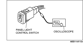
1. Measure the voltage at each terminal (other than terminal D).
2. Disconnect the panel light control switch connector.
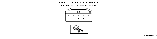
3. Verify that continuity at terminal D is as indicated in the Terminal Voltage Table (Reference).
|
Terminal
|
Signal
|
Connected to
|
Test condition
|
Voltage (V)/Continuity
|
Inspection item(s)
|
|
|---|---|---|---|---|---|---|
|
D
|
Illumination
|
Each illumination
|
Inspect using an oscilloscope.
(See Terminal D inspection.)
|
-
|
• Each illumination
• Related harness
|
|
|
F
|
TNS
|
TNS relay
|
Headlight switch is at TNS or headlight position.
|
B+
|
• TNS relay (See RELAY INSPECTION.)
• ILLUMI 10A fuse
• Related harness
|
|
|
Other
|
0
|
|||||
|
H
|
Ground
|
GND
|
Under any condition: Inspect for continuity to ground.
|
Yes
|
• GND
• Related harness
|
|
1. Measure the wave pattern of the terminal D on the panel light control switch using an oscilloscope.
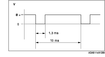
2. Set the headlight switch to either the TNS or headlight position.
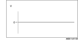
3. Set the panel light control switch to the brightest position.
4. Verify that the pattern on the screen is as shown in the figure.
5. Verify that the pattern on the screen matches the pattern shown in the figure as the panel light control switch is gradually turned to the darkest position.