STEERING WHEEL AND COLUMN REMOVAL/INSTALLATION [L.H.D.]
id0613008014a1
-
Warning
-
• The steering column (EPS motor) temperature increases directly after continuous turning of the steering mechanism which could cause burns if it is touched.Before performing any servicing, verify that the steering column has cooled off.
-
Caution
-
• If work is performed such as the removal/installation of the steering column, disconnection of the intermediate shaft, or disconnection of the steering gear (pinion shaft), the EPS will not operate properly if the installation is performed with the steering shaft rotated 360 degrees by mistake.If the steering gear (pinion shaft) is disengaged, make sure that the steering shaft does not rotate (hold in place) until the intermediate shaft is installed to the steering gear (pinion shaft).
• If the EPS control module configuration is not completed, the EPS will not operate properly.If the steering column (EPS control module) is replaced, always perform the EPS control module configuration so that the EPS operates properly.
• If the EPS steering angle calibration is not completed, the EPS will not operate properly.After completing the following work, if the EPS warning light illuminates or flashes when the steering wheel is turned lock-to-lock with the engine started, always carry out the EPS steering angle calibration so that the EPS operates properly.
-
― Steering column (EPS control module) removal/installation
― Intermediate shaft disconnection
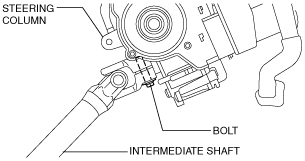
• The joint bolt for the steering column and intermediate shaft shown in the figure cannot be reused and a new bolt cannot be obtained. Therefore, never loosen or remove the bolt. If the bolt is mistakenly loosened or removed, replace the steering column assembly.
• If the steering column is dropped it could result in internal damage to the EPS control module, therefore be careful not to drop it.Replace the steering column if it is subjected to an impact.
1. Remove the side wall. (See SIDE WALL REMOVAL/INSTALLATION.)
2. Remove the shift lever knob (MTX vehicles). (See MANUAL TRANSAXLE SHIFT MECHANISM REMOVAL/INSTALLATION [F35M-R].) (See MANUAL TRANSAXLE SHIFT MECHANISM REMOVAL/INSTALLATION [B65M-R].)
3. Remove the front console component. (See FRONT CONSOLE COMPONENT REMOVAL/INSTALLATION.)
4. Remove the front scuff plate (LH). (See FRONT SCUFF PLATE REMOVAL/INSTALLATION.)
5. Remove the front side trim (LH). (See FRONT SIDE TRIM REMOVAL/INSTALLATION.)
6. Disconnect the bonnet release lever from the lower panel. (See BONNET LATCH AND RELEASE LEVER REMOVAL/INSTALLATION.)
7. Remove the lower panel. (See LOWER PANEL REMOVAL/INSTALLATION.)
8. Remove the heater duct (LH). (See HEAT DUCT COMPONENT REMOVAL/INSTALLATION.)
9. Remove in the order indicated in the table.
10. Install in the reverse order of removal.
11. If the steering lock component is replaced on vehicles with the advanced keyless and start system, perform programming for the immobilizer system related parts. (See IMMOBILIZER SYSTEM-RELATED PARTS PROGRAMMING [ADVANCED KEYLESS AND START SYSTEM].)
12. After installation, perform the following procedure.
-
Replacing the steering column
-
2. Start the engine, and verify that the EPS warning light flashes.
3. Turn the steering wheel lock-to-lock, and then position the wheels in the straight-ahead position.
4. Verify that the EPS warning light turns off.
-
Steering column removal/installation or intermediate shaft disconnection
-
1. Start the engine and turn the steering wheel lock-to-lock.
|
1
|
Driver-side air bag module
|
|
2
|
Lockbolt
|
|
3
|
Steering wheel
|
|
4
|
Column cover
|
|
5
|
Clock spring, combination switch
|
|
6
|
Bracket (MTX vehicles)
|
|
7
|
Steering shaft cover
|
|
8
|
Interlock cable (ATX vehicles)
|
|
9
|
Steering column component
|
|
10
|
Steering lock mounting bolt
|
|
11
|
Steering lock component
|
|
12
|
Coil antenna
|
|
13
|
Key cylinder (vehicles with advanced keyless system)
|
|
14
|
Ignition switch
|
|
15
|
Steering lock
|
|
16
|
Steering column
|
Steering Wheel Removal Note
-
Caution
-
• Do not try to remove the steering wheel by hitting the shaft with a hammer. The steering column will be damaged.
1. Set the vehicle wheels in the straight-ahead position.
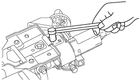
2. Remove the steering wheel using any commercially available puller.
Steering Column Component Removal Note
-
Caution
-
• The EPS will not operate correctly if the steering shaft is installed after it has been rotated once accidentally. When the steering column is not replaced, remove the key and lock the steering wheel before servicing. Do not release the steering lock until the steering column is installed unless replacing the steering lock.
• Always lock the tilt lever to prevent damage to the steering column.In addition, do not unlock the tilt lever until after the steering column installation is completed.
• If the steering column is removed, remove it according to the procedure to prevent damage to intermediate shaft that could result if the steering column is removed in the incorrect order.
1. Remove the key and lock the steering wheel to immobilize the steering shaft.
2. Lock the tilt lever.
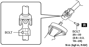
3. Remove the bolt, disconnect the intermediate shaft from the steering gear (pinion shaft).
4. Remove the nut, and then remove the steering column component from the dashboard member.
Steering Lock Mounting Bolt, Steering Lock Component Removal Note
-
Caution
-
• If the steering lock component is removed, the steering shaft cannot be locked and may rotate. The EPS will not operate correctly if the steering shaft is installed after it has been rotated once accidentally. Therefore, if the steering column is not replaced, be careful not to rotate the steering shaft (hold it in place) until it has been installed.
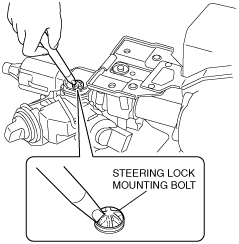
1. Secure the steering shaft and the column area using a cord or tape to prevent the steering shaft from rotating.
2. Make grooves in the heads of the steering lock mounting bolts using a small chisel and rotate them counterclockwise while hitting them.
-
Caution
-
• To prevent the steering column from being damaged, perform the work carefully avoiding impact when removing the steering lock mounting bolts.
3. Remove the bolts, then remove the steering lock component from the steering column.
Key Cylinder Removal Note
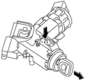
1. Insert the key into the key cylinder and turn it to the ACC position.
2. Insert a pin from the position indicated by the arrow in the figure, and while pressing the lock lever with the pin, remove the key cylinder from the steering lock component.
Key Cylinder Removal Note
1. Insert the key into the key cylinder and turn it to the ACC position.
2. Install the key cylinder to the steering lock.
Steering Lock Component, Steering Lock Mounting Bolt Installation Note
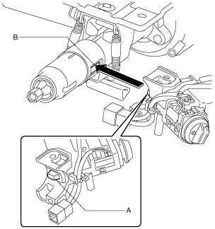
1. Assemble section A of the steering lock component to the section B of the steering column.
2. Temporarily install the steering lock component to the steering column using a new steering lock mounting bolt.
3. Tighten the steering lock mounting bolt until the head breaks off.
Steering Column Component Installation Note
-
Caution
-
• If the steering column is installed, install it according to the procedure to prevent damage to intermediate shaft that could result if the steering column is installed in the incorrect order.
• Do not unlock the tilt lever until after the steering column installation is completed to prevent damage to the steering column.
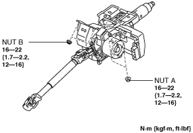
1. Temporarily install the steering column component to the dashboard member using nuts A and B.
2. Tighten the nuts in the order of nut A and nut B.
3. Insert the intermediate shaft into the steering gear (pinion shaft) to the position shown in the figure, and tighten it using a new bolt.
Bracket Installation Note
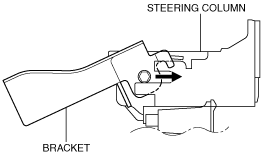
1. With the bracket rotated, insert it until it protrudes as shown in the figure.
2. Rotate the bracket in the direction of the arrow shown in the figure.
3. Verify that the bracket is assembled to the steering column with it locked against rotation as shown in the figure, then tighten the nut to the specified torque.
Steering Wheel Installation Note
1. Set the vehicle wheels in the straight-ahead position, and install the steering wheel using a new lock bolt.