 |
am2zzw00003063
ENGINE REMOVAL/INSTALLATION [MZ-CD 1.4 DI Turbo]
id0110b8800400
1. Complete the "Fuel Line Safety Procedure". (See BEFORE SERVICE PRECAUTION [MZ-CD 1.4 DI Turbo].)
2. Remove the battery. (See BATTERY REMOVAL/INSTALLATION [MZ-CD 1.4 DI Turbo].)
3. Remove the battery tray. (See PCM REMOVAL/INSTALLATION [MZ-CD 1.4 DI Turbo].)
4. Drain the engine coolant. (See ENGINE COOLANT REPLACEMENT [MZ-CD 1.4 DI Turbo].)
5. Remove the front wheels and tires. (See GENERAL PROCEDURES (SUSPENSION).)
6. Remove the drive belt. (See DRIVE BELT REPLACEMENT [MZ-CD 1.4 DI Turbo].)
7. Disconnect the radiator hose.
8. Remove the air cleaner cover, fresh-air duct and air hose. (See INTAKE-AIR SYSTEM REMOVAL/INSTALLATION [MZ-CD 1.4 DI Turbo].)
9. Remove the fuel filter protector. (See FUEL FILTER REMOVAL/INSTALLATION [MZ-CD 1.4 DI Turbo].)
10. Disconnect the fuel hose.
11. Set the cooler pipe and cooler hose (LO) out of the way. (With A/C) (See REFRIGERANT LINE REMOVAL/INSTALLATION.)
12. Remove the A/C compressor with the pipes still connected. (With A/C) (See A/C COMPRESSOR REMOVAL/INSTALLATION.)
13. Disconnect the front drive shafts. (See DRIVE SHAFT REMOVAL/INSTALLATION [MZ-CD 1.4 DI Turbo, MZ-CD 1.6 (Y6)].)
14. Remove the front crossmember. (See FRONT CROSSMEMBER REMOVAL/INSTALLATION.)
15. Disconnect the shift cable. (See MANUAL TRANSAXLE REMOVAL/INSTALLATION [B65M-R (MZ-CD 1.4 DI Turbo)].)
16. Disconnect the vacuum hose and heater hose.
17. Disconnect the wiring harness from the engine side.
18. Remove the oil level gauge pipe.
19. Remove the catalytic converter and front pipe. (See EXHAUST SYSTEM REMOVAL/INSTALLATION [MZ-CD 1.4 DI Turbo].)
20. Remove the clutch pipe connector. (See MANUAL TRANSAXLE REMOVAL/INSTALLATION [B65M-R (MZ-CD 1.4 DI Turbo)].)
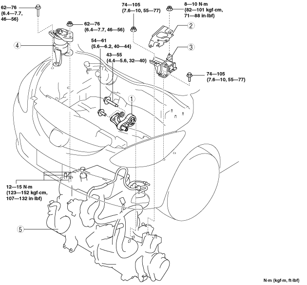
21. Remove in the order indicated in the table.
22. Install in the reverse order of removal.
23. Bleed the air from the clutch fluid. (See CLUTCH FLUID AIR BLEEDING/REPLACEMENT [B65M-R].)
24. Start the engine. and inspect and adjust the following:
am2zzw00003063
|
|
1
|
No.1 Engine mount rubber
|
|
2
|
Battery tray bracket
|
|
3
|
No.4 Engine mount rubber
|
|
4
|
No.3 Engine mount
|
|
5
|
Engine, transaxle
|
No.1 Engine Mount Removal Note
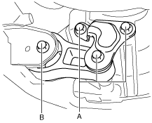
1. Remove the installation bolts (A) from below the vehicle.
am2zzw00003068
|
2. Loosen the installation bolt (B).
3. Remove the No.1 engine mount rubber and the front crossmember as a single unit. (See FRONT CROSSMEMBER REMOVAL/INSTALLATION.)
No.3 Engine Mount, No.4 Engine Mount Rubber Removal Note
am2zzw00003064
|
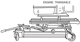
1. Secure the engine and the transaxle using an engine jack.
am2zzw00002587
|
No.3 Engine Mount, No.4 Engine Mount Rubber Installation Note
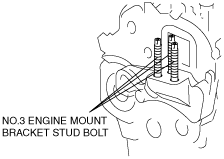
1. Tighten the No. 3 engine mount bracket stud bolts.
am2zzw00003130
|
2. Secure the engine and the transaxle using an engine jack.
am2zzw00002587
|
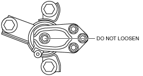
3. Install the No.3 engine mount, and then temporarily tighten the installation bolts and nuts.
4. Tighten the installation nuts and bolts by order of A, B.
am2zzw00003065
|
5. Install the No.4 engine mount rubber, and then temporarily tighten the installation bolts and nuts.
6. Tighten the installation nuts and bolts by order of A, B.
am2zzw00001798
|
No.1 Engine Mount Installation Note
1. Install the No.1 Engine mount rubber, and then temporarily tighten the installation bolts.
2. Tighten the installation bolts (A).
am2zzw00003068
|
3. Tighten the installation bolt (B).
4. Remove the engine jack.