 |
am2zzw00004035
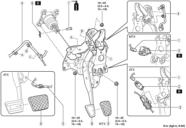
BRAKE PEDAL REMOVAL/INSTALLATION [ZJ, ZY]
id0411001933h1
1. Remove the accelerator pedal. (See ACCELERATOR PEDAL REMOVAL/INSTALLATION [ZJ, ZY].)
2. Remove in the order indicated in the table.
3. Install in the reverse order of removal.
L.H.D.
am2zzw00004035
|
|
1
|
Brake switch connector
|
|
2
|
Brake switch
|
|
3
|
Interlock unit (ATX)
(See Interlock Unit Removal Note.)
|
|
4
|
Wiring harness
|
|
5
|
Interlock cable (ATX)
|
|
6
|
Snap pin
|
|
7
|
Clevis pin
|
|
8
|
Brake pedal
(See Brake Pedal Removal Note.)
|
|
9
|
Pedal pad
|
R.H.D.
am2zzw00004036
|
|
1
|
Brake switch connector
|
|
2
|
Brake switch
|
|
3
|
Interlock unit (ATX)
(See Interlock Unit Removal Note.)
|
|
4
|
Wiring harness
|
|
5
|
Interlock cable (ATX)
|
|
6
|
Snap pin
|
|
7
|
Clevis pin
|
|
8
|
Brake pedal
(See Brake Pedal Removal Note.)
|
|
9
|
Pedal pad
|
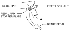
Interlock Unit Removal Note
1. Before removing the interlock unit, measure length A (between interlock unit and pedal arm stopper plate) and note it down for reference in installation.
am2zzw00001131
|
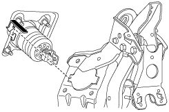
Brake Pedal Removal Note
1. Remove the brake pedal as shown in the figure.
am2zzw00004037
|
Brake Pedal Installation Note
1. Install the brake pedal as shown in the figure.
am2zzw00004038
|
Interlock Unit Installation Note
1. Verify that length A measured at installation has not changed and install the interlock unit.
am2zzw00001131
|
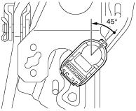
Brake Switch Installation Note (MTX)
1. Inspect the brake pedal. (See BRAKE PEDAL INSPECTION.)
2. With the brake pedal fully released, insert a new brake switch into the installation hole on the brake pedal.
3. Secure the brake switch by turning it counterclockwise 45°.
am2zzw00002239
|
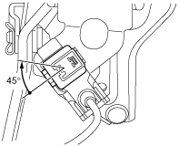
Brake Switch Installation Note (ATX)
1. Install a new brake switch to the interlock unit, and secure by turning it clockwise 45°.
adejjw00004612
|
Brake Switch Connector Installation Note (ATX)
1. Inspect the brake pedal. (See BRAKE PEDAL INSPECTION.)
2. With the brake pedal fully released, install the brake switch connector to the brake switch.