L.H.D.
am2zzw00001181
|

R.H.D.
am2zzw00001658
|
AUTOMATIC TRANSAXLE SHIFT MECHANISM REMOVAL/INSTALLATION
id051800274500
Selector Lever Removal/Installation
1. Disconnect the selector lever component connector.
L.H.D.
am2zzw00001181
|
R.H.D.
am2zzw00001658
|
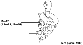
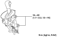
2. Remove the selector lever.
am2zzw00001171
|
am2zzw00001779
|
L.H.D.
am2zzw00001780
|
R.H.D.
am2zzw00001781
|
3. Install in the reverse order of removal.
Selector Cable and Interlock Cable Removal/Installation
1. Disconnect the negative battery cable.
2. Disconnect the selector cable from the manual shaft lever. (See EXHAUST SYSTEM REMOVAL/INSTALLATION [ZJ, ZY].)
3. Disconnect the selector cable from the upper transaxle bracket.
4. Remove the insulator No.1 of the exhaust system. (See EXHAUST SYSTEM REMOVAL/INSTALLATION [ZJ, ZY].)
5. Remove the column cover. (See COLUMN COVER REMOVAL/INSTALLATION.)
6. Remove the side wall.(See SIDE WALL REMOVAL/INSTALLATION.)
7. Remove the front console component.(See FRONT CONSOLE COMPONENT REMOVAL/INSTALLATION.)
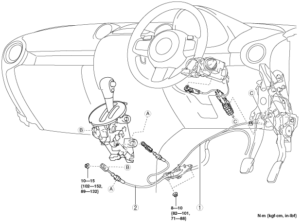
8. Remove in the order indicated in the figure.
9. Install in the reverse order of removal.
L.H.D.
am2zzw00001652
|
R.H.D.
am2zzw00001670
|
|
1
|
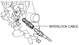
Interlock Cable
|
|
2
|
Selector cable
(See Selector Cable Removal Note.)
|
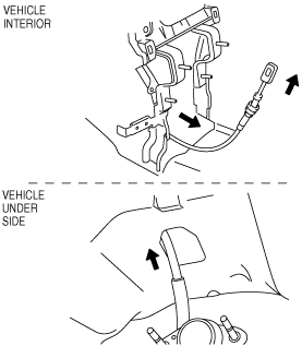
Selector Cable Removal Note
1. Working with two people, one person pushes the ends of the selector cable toward the inside of the vehicle, and at the same time, the other person pulls out the selector cable by pulling the ends of the selector cable.
am2zzw00001625
|
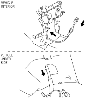
Selector Cable Installation Note
1. Working with two people, one person pushes the ends of the selector cable toward the lower side of the vehicle from the inside, and at the same time, the other person pulls the ends of the selector cable.
am2zzw00001626
|
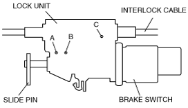
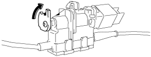
Interlock Cable Installation Note
1. Install the interlock cable to the key cylinder.
2. Install the lock unit to the brake pedal.
am2zzw00001168
|
am2zzw00001169
|
adejjw00002233
|
adejjw00002234
|
am2zzw00001170
|
3. Install the interlock cable to the selector lever.
4. Pull out the pin from the lock unit.
5. Verify that the interlock cable is properly installed.