 |
am2zzw00001261
PID/DATA MONITOR INSPECTION
id050200805600
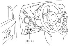
1. Connect the M-MDS to the DLC‐2.
L.H.D.
am2zzw00001261
|
R.H.D.
am2zzw00000606
|
2. After the vehicle is identified, select the following items from the initialization screen of the M-MDS.
3. Select the applicable PID from the PID table.
4. Measure the PID value.
PID/DATA MONITOR AND RECORD function table
|
Monitor item |
Unit/Condition |
Condition/Specification |
Action |
PCM terminal |
|
|---|---|---|---|---|---|
|
GEAR
|
1st/2nd/3rd/4th
|
• 1GR: 1st
• 2GR: 2nd
• 3GR: 3rd
• 4GR: 4th
|
Inspect the following PIDs:
SSA/SS1, SSB/SS2, SSC/SS3, SSD/SS4, SSE_SS5
|
N/A
|
|
|
HTM_CNT
|
—
|
Indicates number of high oil temperature mode (ATF temperature at 130 °C {266 °F} or more) operations
|
—
|
N/A
|
|
|
HTM_DIS
|
km
|
mile
|
Indicates travel distance after operation of high oil temperature mode (ATF temperature at 130 °C {266 °F} or more)
|
—
|
N/A
|
|
LINEDES
|
Pa
|
Idling at P position: approx. 400 kPa
|
Inspect the following PIDs:
TFT, TFTV, TR, TR_SENS, TSS, VSS
|
N/A
|
|
|
LPS
|
A
|
Idling at P position: approx. 950 mA
|
Inspect the pressure control solenoid.
(See SOLENOID VALVE INSPECTION.)
|
1P, 1T
|
|
|
OSS
|
RPM
|
• Vehicle speed 0 km/h {0 mph}: 0 RPM
• Vehicle speed 25 km/h {16 mph}: 200—230 RPM
|
Inspect the VSS.
|
1AX
|
|
|
SSA/SS1
|
%
|
• 4GR: 99%
• Others: 0%
|
Inspect the shift solenoid A.
(See SOLENOID VALVE INSPECTION.)
|
1D
|
|
|
SSB/SS2
|
%
|
• Idling at D range: 99%
• Others: 0%
|
Inspect the shift solenoid B.
(See SOLENOID VALVE INSPECTION.)
|
1H
|
|
|
SSC/SS3
|
%
|
• Idling at D range: 99%
• Others: 0%
|
Inspect the shift solenoid C.
(See SOLENOID VALVE INSPECTION.)
|
1L
|
|
|
SSD/SS4
|
On/Off
|
• P, N position: On
• Others: Off
|
Inspect the shift solenoid D.
(See SOLENOID VALVE INSPECTION.)
|
1K
|
|
|
SSE_SS5
|
On/Off
|
• HOLD mode at L range: On
• Others: Off
|
Inspect the shift solenoid E.
(See SOLENOID VALVE INSPECTION.)
|
1O
|
|
|
TCS
|
On/Off
|
• HOLD switch released: Off
• HOLD switch depressed: On
|
Inspect the HOLD switch.
(See HOLD SWITCH INSPECTION.)
|
1N
|
|
|
TFT
|
°C
|
°F
|
• ATF 20 °C {68 °F}: 20 °C {68 °F}
• ATF 40 °C {104 °F}: 40 °C {104 °F}
• ATF 60 °C {140 °F}: 60 °C {140 °F}
|
Inspect the TFT sensor.
|
1AH
|
|
TFTV
|
V
|
• ATF 20 °C {68 °F}: approx. 3.3 V
• ATF 40 °C {104 °F}: approx. 2.4 V
• ATF 60 °C {140 °F}: approx. 1.5 V
|
Inspect the TFT sensor.
|
1AH
|
|
|
TR
|
P/R/N/D/S/L
|
• P position: P
• R position: R
• N position: N
• D range: D
• S range: S
• L range: L
|
Inspect the TR switch.
|
1AS
|
|
|
TR_SENS
|
V
|
• P position: approx. 4.6 V
• R position: approx. 3.9 V
• N position: approx. 3.3 V
• D range: approx. 2.5 V
• S range: approx. 1.7 V
• L range: approx. 0.9 V
|
Inspect the TR switch.
|
1AS
|
|
|
TSS
|
RPM
|
• Idling: 700—800 RPM
|
Inspect the input/turbine speed sensor.
|
1R, 1V
|
|
