|
1
|
VERIFY FREEZE FRAME DATA HAS BEEN RECORDED
• Has the FREEZE FRAME DATA been recorded?
|
Yes
|
Go to the next step.
|
|
No
|
Record the FREEZE FRAME DATA on the repair order, then go to the next step.
|
|
2
|
VERIFY RELATED REPAIR INFORMATION AVAILABILITY
• Verify related Service Bulletins and/or on-line repair information availability.
• Is any related repair information available?
|
Yes
|
Perform repair or diagnosis according to the available repair information.
• If the vehicle is not repaired, go to the next step.
|
|
No
|
Go to the next step.
|
|
3
|
INSPECT INPUT/TURBINE SPEED SENSOR CONNECTOR FOR POOR CONNECTION
• Turn the ignition switch off.
• Disconnect the input/turbine speed sensor connector.
• Inspect for poor connection (such as damaged/pulled-out pins, corrosion)
• Is there any malfunction?
|
Yes
|
Repair or replace the terminal, then go to Step 8.
|
|
No
|
Go to the next step.
|
|
4
|
INSPECT INPUT/TURBINE SPEED SENSOR CIRCUIT FOR SHORT TO GND
• Turn the ignition switch off.
• Inspect for continuity between the following circuits:
-
― Input/turbine speed sensor terminal A (wiring harness-side) and body GND
― Input/turbine speed sensor terminal B (wiring harness-side) and body GND
• Is there continuity?
|
Yes
|
Repair or replace the wiring harness for a possible short to GND, then go to Step 8.
|
|
No
|
Go to the next step.
|
|
5
|
INSPECT INPUT/TURBINE SPEED SENSOR
• Inspect the input/turbine speed sensor.
• Is there any malfunction?
|
Yes
|
Replace the input/turbine speed sensor, then go to Step 8.
|
|
No
|
Go to the next step.
|
|
6
|
INSPECT PCM CONNECTOR FOR POOR CONNECTION
• Turn the ignition switch off.
• Disconnect the PCM connector.
• Inspect for poor connection (such as damaged/pulled-out pins, corrosion)
• Is there any malfunction?
|
Yes
|
Repair or replace the terminal, then go to Step 8.
|
|
No
|
Go to the next step.
|
|
7
|
INSPECT INPUT/TURBINE SPEED SENSOR CIRCUIT FOR OPEN CIRCUIT
• Turn the ignition switch off.
• Inspect for continuity between the following circuits:
-
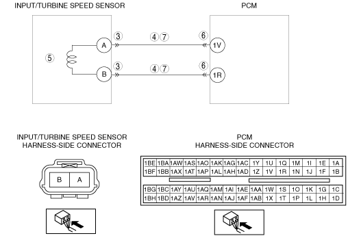
― Input/turbine speed sensor terminal A (wiring harness-side) and PCM terminal 1V (wiring harness-side)
― Input/turbine speed sensor terminal B (wiring harness-side) and PCM terminal 1R (wiring harness-side)
• Is there continuity?
|
Yes
|
Go to the next step.
|
|
No
|
Repair or replace the wiring harness for a possible open circuit, then go to the next step.
|
|
8
|
VERIFY TROUBLESHOOTING OF DTC P0715:00 COMPLETED
• Make sure to reconnect all the disconnected connectors.
• Clear the DTC from the memory using the M-MDS.
• Perform the following procedure to ensure that the DTC has been resolved:
-
― Drive the vehicle at more than 41 km/h {25 mph} for 1 s.
• Is the same DTC present?
|
Yes
|
Replace the PCM, then go to the next step.
|
|
No
|
Go to the next step.
|
|
9
|
VERIFY AFTER REPAIR PROCEDURE
• Perform the “After Repair Procedure”.
• Are any DTCs present?
|
Yes
|
Go to the applicable DTC inspection.
|
|
No
|
DTC troubleshooting completed.
|