 |
am2zzw00000001
MANUAL TRANSAXLE REMOVAL/INSTALLATION [B65M-R (MZ-CD 1.4 DI Turbo)]
id0515h38006h5
1. Disconnect the negative battery cable.
2. Remove the battery and battery tray. (See BATTERY REMOVAL/INSTALLATION [MZ-CD 1.4 DI Turbo].)
3. Remove the wheels and tires.
4. Remove the fresh-air duct No.1. (See INTAKE-AIR SYSTEM REMOVAL/INSTALLATION [MZ-CD 1.4 DI Turbo].)
5. Remove the air hose No.1. (See INTAKE-AIR SYSTEM REMOVAL/INSTALLATION [MZ-CD 1.4 DI Turbo].)
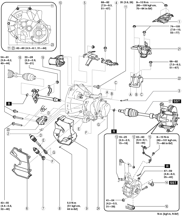
6. Remove in the order indicated in the table.
7. Install in the reverse order of removal.
8. Add the specified amount of specified transaxle oil. (See TRANSAXLE OIL INSPECTION [B65M-R].)
am2zzw00000001
|
|
1
|
Battery tray bracket
|
|
2
|
Back-up light switch connector
|
|
3
|
Clutch pipe
(See Clutch Pipe Removal Note.)
|
|
4
|
Clutch pipe bracket
|
|
5
|
Cable bracket
|
|
6
|
Cable box cover
|
|
7
|
Shift cable
|
|
8
|
Select cable
|
|
9
|
Cable box
|
|
10
|
Starter
|
|
11
|
Transaxle mounting bolt (upper side)
|
|
12
|
Nut (stabilizer control link upper side)
|
|
13
|
Bolt (brake hose bracket)
|
|
14
|
Tie-rod end ball joint
|
|
15
|
ABS wheel-speed sensor
|
|
16
|
Front lower arm ball joint
|
|
17
|
Drive shaft (LH)
|
|
18
|
Drive shaft (RH)
|
|
19
|
Joint shaft
|
|
20
|
No.1 engine mount
|
|
21
|
No.4 engine mount rubber
|
|
22
|
No.4 engine mount bracket
|
|
23
|
Transaxle mounting bolt (lower side)
|
|
24
|
Manual transaxle
|
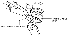
Shift Cable and Select Cable Removal Note
1. Remove the both shift cable end and select cable end using a fastener remover.
am2zzw00004078
|
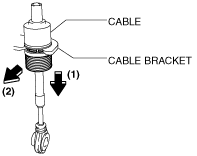
2. Remove the shift and select cable in the order shown in the figure.
am2zzw00004079
|
ABS Wheel-Speed Sensor Removal Note
1. Remove the ABS wheel-speed sensor installation bolt, then remove the ABS wheel-speed sensor from the steering knuckle.
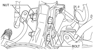
2. Remove the bolts and nuts shown in the figure, then disconnect the steering knuckle from the shock absorber.
am2zzw00004080
|
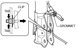
3. While pressing the tabs (2 locations) of the ABS wheel-speed sensor wiring harness clip, remove the ABS wheel-speed sensor wiring harness from the shock absorber.
am2zzw00004081
|
4. Remove the ABS wheel-speed sensor wiring harness grommet from the shock absorber.
5. Move the ABS wheel-speed sensor to a place out of the way.
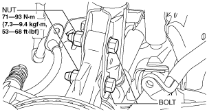
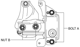
6. Install the steering knuckle to the shock absorber, insert the bolts from the direction shown as follows, then tighten them to the specified torque.
am2zzw00004082
|
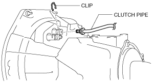
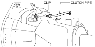
Clutch Pipe Removal Note
1. Remove the clip from the clutch release cylinder.
am2zzw00004083
|
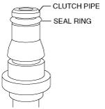
2. Remove the clutch pipe connector straight.
3. Verify that the seal ring is removed together with the clutch pipe.
am2zzw00003993
|
Transaxle Mounting Bolt (lower side) Removal Note
1. Because the bolt shown in the figure cannot be pulled out completely, move the bolt in the direction of the arrow, and then remove the manual transmission.
am2zzw00002905
|
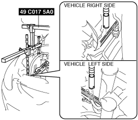
No.4 Engine Mount Removal Note
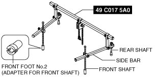
1. Install front foot No.2 to the left/right front shaft of the SST (49 C017 5A0).
am2zzw00004084
|
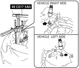
2. As shown in the figure, set the rear shafts of the SST to the left and right shock absorber upper bolts.
am2zzw00004085
|
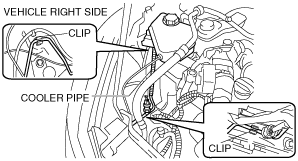
3. Remove the coolant reserve tank from the clip and set it out of the way.
4. Remove the cooler pipe from the clips and set it out of the way to prevent interference between the SST and the front shaft.
am2zzw00004086
|
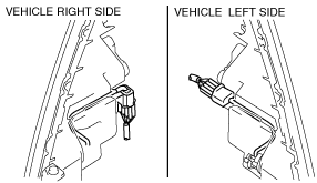
5. Remove the front combination light connector from the clip and set it out of the way to prevent interference between the SST and the front shaft. (Except vehicles with HID)
am2zzw00004087
|
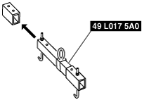
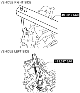
6. As shown in the figure, set the front shaft groove of the SST to the folded part of the left and right body frames.
am2zzw00004088
|
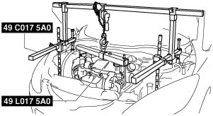
7. Remove the oil filler cap.
8. Set the SST as shown in the figure.
am2zzw00002873
|
9. Hang the engine using the SST.
am2zzw00003103
|
10. Adjust the height of the left and right side bars so that they are leveled, then tighten each part of the SST.
am2zzw00004089
|
11. Verify that the SST is properly set and the engine is securely hung.
12. Remove the No.4 engine mount.
No.4 Engine Mount Installation Note
1. Tighten the bolt A.
am2zzw00004090
|
2. Adjust the SST (engine support) so that the stud bolts of the No.4 engine mount bracket and the bolt holes of the No.4 engine mount rubber are aligned.
3. Using a jack, raise the transaxle until the stud bolts of the No.4 engine mount bracket project from the bolt holes of the No.4 engine mount rubber.
4. Tighten the No.4 engine mount rubber in the order of nut B and bolt A.
am2zzw00004091
|
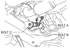
No.1 Engine Mount Installation Note
1. Adjust the SST (engine support), and align the hole of the No.1 engine mount with the bolt hole of transaxle.
2. Tighten the bolt A,B from manual transaxle.
am2zzw00004092
|
3. Tighten the bolt C.
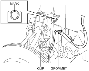
ABS Wheel-Speed Sensor Installation Note
1. Install the ABS wheel-speed sensor wiring harness grommet to the shock absorber as shown in the figure.
am2zzw00004093
|
2. Install the ABS wheel-speed sensor wiring harness clip to the shock absorber.
3. Install the ABS wheel-speed sensor to the steering knuckle, then tighten the bolt (ABS wheel-speed sensor) to the specified torque.
4. Verify that the ABS wheel-speed sensor wiring harness is not twisted.
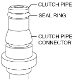
Clutch Pipe Installation Note
1. Verify that the seal ring is installed to the groove at the end of the clutch pipe.
am2zzw00003991
|
2. Install the clip from the clutch release cylinder.
am2zzw00004094
|
3. Insert the clutch pipe connector straight.
4. Pull the clutch pipe to verify that it does not come off, and reinsert it completely.