DTC 14 [FULL-AUTO AIR CONDITIONER]
id0702c1802900
Except General (L.H.D.) Specs.
DTC 14 |
ECT sensor (present malfunction) |
---|---|
DETECTION CONDITION
|
• Engine coolant temperature signal input from the ECT sensor is -40 °C {40 °F} or less, or 140 °C {284 °F} or more.
|
POSSIBLE CAUSE
|
• ECT sensor malfunction
• PCM malfunction
• BCM malfunction
• Instrument cluster malfunction
• Open or short circuit in wiring harness between ECT sensor and PCM
• Malfunction in wiring harness between the PCM and instrument cluster related to CAN communication
• Open or short circuit in wiring harness between instrument cluster and climate control unit
• Climate control unit malfunction
|
![]() |
Diagnostic Procedure
STEP |
INSPECTION |
ACTION |
|
---|---|---|---|
1
|
INSPECT FOR PCM DTCs
• Connect the M-MDS to the DLC-2.
• Inspect for PCM DTCs
• Are DTCs P0117:00, P0118:00 output?
|
Yes
|
Perform the corresponding DTC inspection.
(See DTC TABLE [ZJ, ZY].)
|
No
|
Go to the next step.
|
||
2
|
INSPECT FOR INSTRUMENT CLUSTER DTCs
• Inspect for instrument cluster DTCs
• Are DTCs output?
|
Yes
|
Perform the corresponding DTC inspection.
|
No
|
Go to the next step.
|
||
3
|
VERIFY INSTRUMENT CLUSTER CONNECTOR CONDITION
• Turn the ignition switch to the LOCK position.
• Disconnect the instrument cluster connector.
• Inspect the connector and terminals (corrosion, damage, pin disconnection).
• Are the connector and terminals normal?
|
Yes
|
Go to the next step.
|
No
|
Repair/replace the connector or terminal.
After repair procedure, go to Step 7.
|
||
4
|
VERIFY CLIMATE CONTROL UNIT CONNECTOR CONDITION
• Disconnect the climate control unit connector.
• Inspect the connector and terminals (corrosion, damage, pin disconnection).
• Are the connector and terminals normal?
|
Yes
|
Go to the next step.
|
No
|
Repair/replace the connector or terminal.
After repair procedure, go to Step 7.
|
||
5
|
INSPECT SERIAL COMMUNICATION CIRCUIT FOR OPEN CIRCUIT
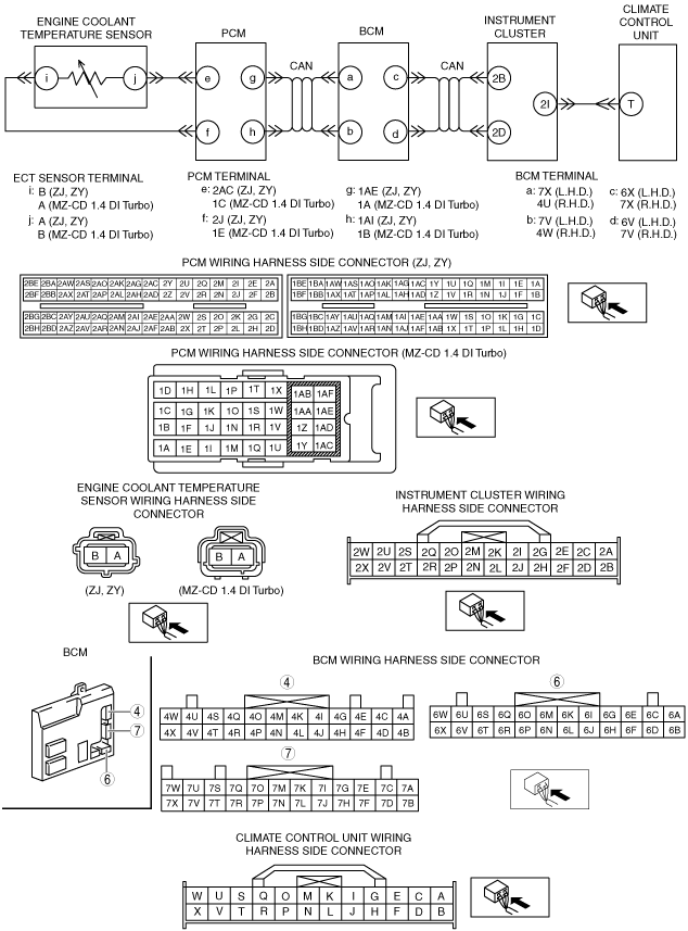
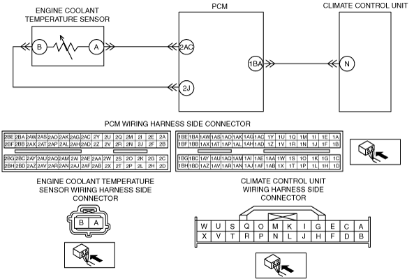
• Inspect the wiring harness between instrument cluster connector terminal 2I and climate control unit connector terminal T.
• Is there continuity?
|
Yes
|
Go to the next step.
|
No
|
Repair/replace the malfunctioning vehicle wiring harness.
After repair procedure, go to Step 7.
|
||
6
|
INSPECT SERIAL COMMUNICATION CIRCUIT FOR SHORT CIRCUIT
• Inspect the wiring harness for continuity between climate control unit connector terminal T and body ground.
• Is there continuity?
|
Yes
|
Repair/replace the malfunctioning vehicle wiring harness.
After repair procedure, go to Step 7.
|
No
|
Go to the next step.
|
||
7
|
VERIFY THAT SAME DTC IS NOT OUTPUT AGAIN
• Reconnect the disconnected connectors.
• Verify DTCs.
• Is DTC 14 output?
|
Yes
|
Repeat the inspection from Step 1.
• If the malfunction does not recur, go to the next step.
• If the malfunction recurs, replace the climate control unit.
|
No
|
Go to the next step.
|
||
8
|
VERIFY THAT NO OTHER DTCs ARE PRESENT
• Verify other DTC displayed.
• Are any other DTCs output?
|
Yes
|
Perform the corresponding DTC inspection.
|
No
|
DTC troubleshooting completed.
|
General (L.H.D.) Specs.
DTC 14 |
ECT sensor (present malfunction) |
---|---|
DETECTION CONDITION
|
• Engine coolant temperature signal input from the ECT sensor is -40 °C {40 °F} or less, or 140 °C {284 °F} or more.
|
POSSIBLE CAUSE
|
• ECT sensor malfunction
• PCM malfunction
• Open or short circuit in wiring harness between ECT sensor and PCM
• Open or short circuit in wiring harness between PCM and climate control unit
• Climate control unit malfunction
|
![]() |
Diagnostic Procedure
STEP |
INSPECTION |
ACTION |
|
---|---|---|---|
1
|
INSPECT FOR PCM DTCs
• Connect the M-MDS to the DLC-2.
• Inspect for PCM DTCs
• Are DTCs P0117:00, P0118:00 output?
|
Yes
|
Perform the corresponding DTC inspection.
(See DTC TABLE [ZJ, ZY].)
|
No
|
Go to the next step.
|
||
2
|
VERIFY PCM CONNECTOR CONDITION
• Turn the ignition switch to the LOCK position.
• Disconnect the PCM connector.
• Inspect the connector and terminals (corrosion, damage, pin disconnection).
• Are the connector and terminals normal?
|
Yes
|
Go to the next step.
|
No
|
Repair/replace the connector or terminal.
After repair procedure, go to Step 6.
|
||
3
|
VERIFY CLIMATE CONTROL UNIT CONNECTOR CONDITION
• Disconnect the climate control unit connector.
• Inspect the connector and terminals (corrosion, damage, pin disconnection).
• Are the connector and terminals normal?
|
Yes
|
Go to the next step.
|
No
|
Repair/replace the connector or terminal.
After repair procedure, go to Step 6.
|
||
4
|
INSPECT SERIAL COMMUNICATION CIRCUIT FOR OPEN CIRCUIT
• Inspect the wiring harness between PCM connector terminal 1BA and climate control unit connector terminal N.
• Is there continuity?
|
Yes
|
Go to the next step.
|
No
|
Repair/replace the malfunctioning vehicle wiring harness.
After repair procedure, go to Step 6.
|
||
5
|
INSPECT SERIAL COMMUNICATION CIRCUIT FOR SHORT CIRCUIT
• Inspect the wiring harness for continuity between climate control unit connector terminal N and body ground.
• Is there continuity?
|
Yes
|
Repair/replace the malfunctioning vehicle wiring harness.
After repair procedure, go to Step 6.
|
No
|
Go to the next step.
|
||
6
|
VERIFY THAT SAME DTC IS NOT OUTPUT
• Reconnect the disconnected connectors.
• Verify DTCs.
• Is DTC 14 output?
|
Yes
|
Repeat the inspection from Step 1.
• If the malfunction does not recur, go to the next step.
• If the malfunction recurs, replace the climate control unit.
|
No
|
Go to the next step.
|
||
7
|
VERIFY THAT NO OTHER DTCs ARE PRESENT
• Verify other DTCs displayed.
• Are any other DTCs output?
|
Yes
|
Perform the corresponding DTC inspection.
|
No
|
DTC troubleshooting completed.
|